8.3.1 M00 MAIN MENU
Menu scope
This submenu includes the following software parameters:
• Home
• Selection of required value
• Regulation restart value
• Language selection
• Date and time setup
• Auto - start
• Operating hours
HOME
The information shown on the display depends on the selection done in parameter 105
MODE; for more details, see P105 MODE (page 55)
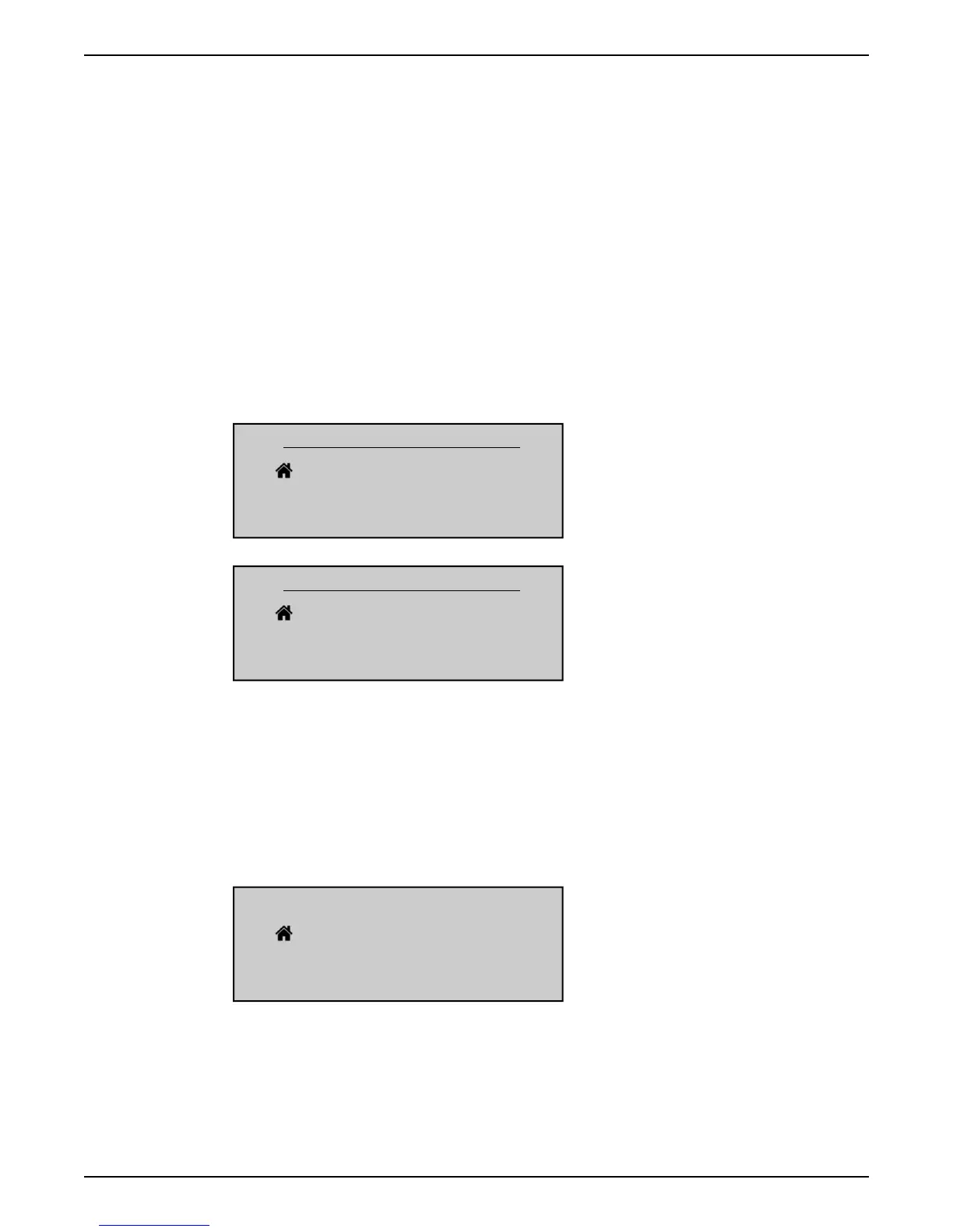
When P105 MODE is set to Controller or Actuator, display shows the following
information:
CONTROLLER
Actual Value
Status HV Output Freq.
PREV START STOP NEXT
ACTUATOR
Actual Value
Status HV Output Freq.
PREV START STOP NEXT
where:
• Actual value: is the input signal supplied by the selected transducer (set by menu 400)
• Status HV: is the HYDROVAR status (ON / OFF / STOP) depending on manual setting
on push buttons and external contact X1/18-19)
• Output frequency: current frequency supplied by the drive to the motor
• PREV/START/STOP/NEXT: actual functions of the related push buttons
When parameter 105 MODE is set to Cascade Relay, display shows the following
information:
CASCADE RELAY #1+4
Actual Value
Status HV Output Freq.
PREV START STOP NEXT
where:
• Cascade Relay: is the value of parameter 105
• #1+4: is the indication that the system is running with 1 Master (#1) and, for example, 4
fixed speed pumps (+4)
• Actual value: is the input signal supplied by the selected transducer (set by menu 400)
8 Programming
HVL 2.015-4.220 Installation, Operation, and Maintenance Manual 45