Control cables
All control cables that are connected to the control board must be screened.
External volt free contacts must be suitable for switching < 10 VDC.
NOTICE:
If unscreened control cables are used, then signal interference with the incoming signals
and the function of the unit can be compromised.
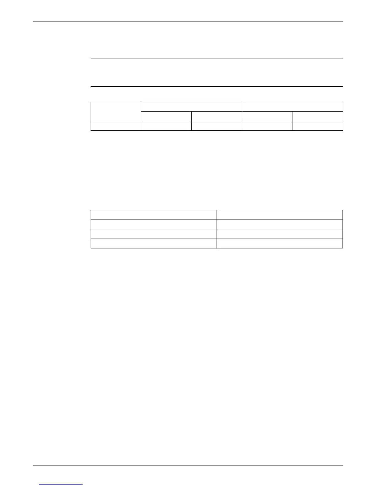
Table 4: Recommended control cables
Hydrovar Control
Cables
Copper section Tightening torque
mm
2
AWG Nm lb-in.
All I/O conductors 0.2 ÷ 1.6 25÷ 16 0.5–0.6 4.5–5.4
6.4 EMC compatibility
6.4.1 EMC requirements
Hydrovar fulfills the product standard EN61800-3:2004 + A1:2012, which defines
categories (C1 to C4) for device application areas.
Depending on the motor cable length, a classification of Hydrovar by category (based on
EN61800-3) is reported in the following table:
Table 5: EMC categories
HVL Hydrovar classification by categories based on 61800-3
2.015 ÷ 2.040 C1 (*)
3.015 ÷ 3.110 C2 (*)
4.015 ÷ 4.220 C2 (*)
(*) 0,75 motor cable length; contact Xylem for further information
NOTICE: No external EMC filters are required to make Hydrovar compliant with the limit
values of each category reported in the preceding table; motor cable shall be shielded.
6.4.2 Wiring the cables
To ensure electromagnetic compatibility the following points must be observed for cable
installation:
• Ground cables should be as short as possible and with lowest impedance.
• Signal cables should be screened types to prevent disturbances from outside. Connect
the shield to ground on one end only (to prevent ground loops), preferably to
HYDROVAR GND using the pre mounted cable-clips; to connect a shield with lowest
impedance to ground, remove the insulation from the signal cable and connect the
shield to ground, as shown in the following image.
• Shielded Motor cable should be as short as possible; connect the shield to ground on
both ends!
6 Electrical Installation
30 HVL 2.015-4.220 Installation, Operation, and Maintenance Manual