Table 6: PTC terminals
Terminals Description
X1/7 PTC or thermal switch input
X1/8 PTC or thermal switch input (Ground)
6.6.2 Input for emergency basic operations
Terminals X1/20 and X1/21 are used to connect an external switch which forces (when
closed) Hydovar to perform a manual start-up till reaching the maximum frequency (fixed
speed) set by par. 245 "Maximum Frequency
Table 7: SL terminals
Terminals Description
X1/20 External switch (SOLO RUN) input
X1/21 External switch (SOLO RUN) input (Ground)
6.6.3 Digital and analog I/O
Several terminals, from X1/1 to X1/24, are used to connect analog and digital I/Os to
correspondent input signals, most of them configurable by specific parameters.
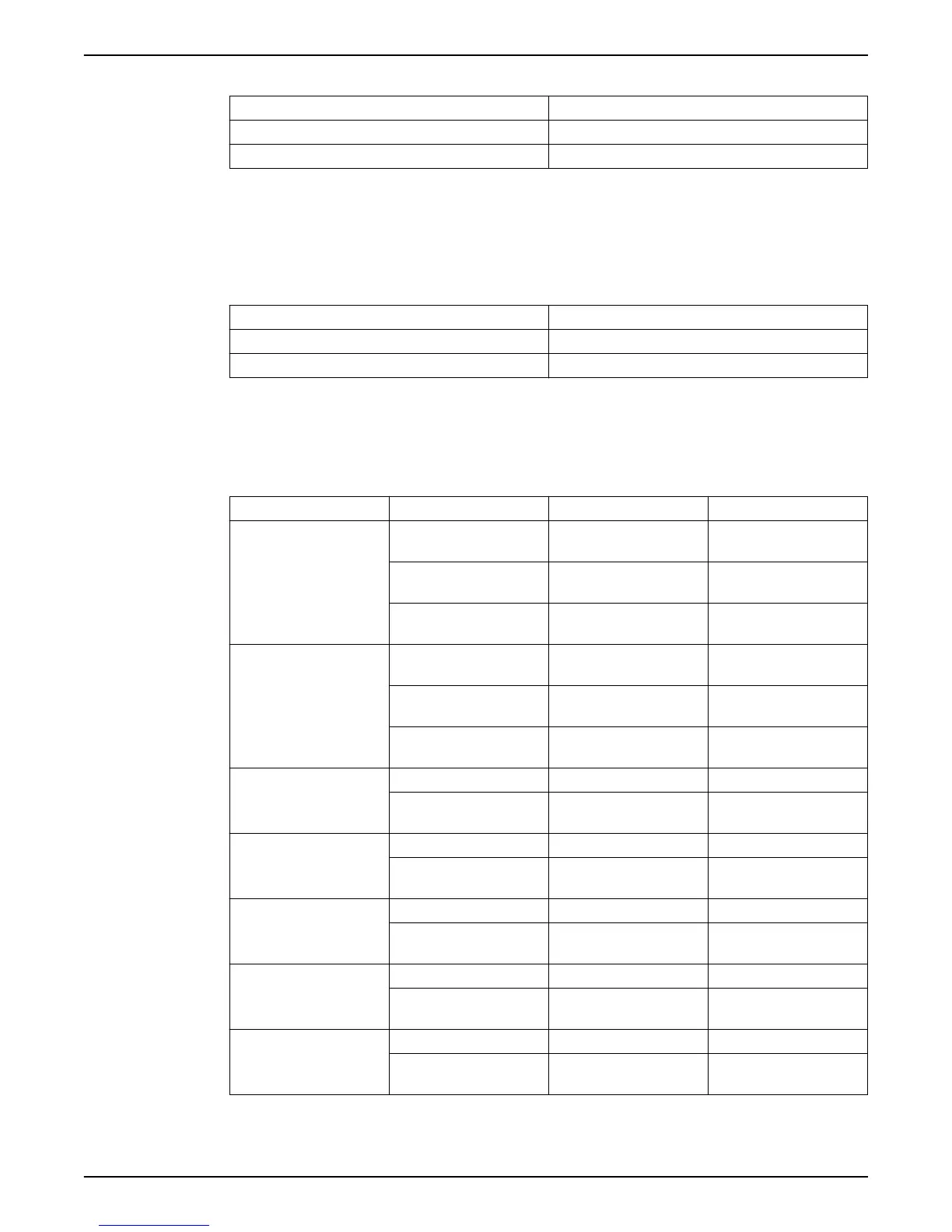
Table 8: I/O terminals
Item Terminals Description Comments
Sensor 1
X1/1 Power supply for external
sensor 1
24VDC, Σ max. 100mA
X1/2 Actual value current/voltage
input sensor 1
0-20mA / 4-20mA / 0-10
VDC / 2-10 VDC
X1/3 Ground for external sensor
1
GND, electronic ground (for
X1/2)
Sensor 2
X1/4 Power supply for external
sensor 2
24VDC, Σ max. 100mA
X1/5 Actual value current/voltage
input sensor 2
0-20mA / 4-20mA / 0-10
VDC / 2-10 VDC
X1/6 Ground for external sensor
2
GND, electronic ground (for
X1/5)
Auxiliary
X1/9 Auxiliary voltage supply 10VDC, max. 3mA
X1/10 Ground for auxiliary voltage
supply
GND, electronic ground (for
X1/9)
Digital Input
X1/14 Configurable digital input 1 Active low
X1/15 Ground for configurable
digital input 1
GND, electronic ground (for
X1/14)
Low water
X1/16 Low water input Active low
X1/17 Ground for low water input GND, electronic ground (for
X1/16)
External ON/OFF
X1/18 External ON/OFF input Active low
X1/19 Ground for external ON/OFF
input
GND, electronic ground (for
X1/18)
External fan (Not to be
used: only for Wall
Mounting kit connection!)
X1/22 External fan control
X1/23 Ground for external fan
control
GND, electronic ground (for
X1/22)
6 Electrical Installation
36 HVL 2.015-4.220 Installation, Operation, and Maintenance Manual