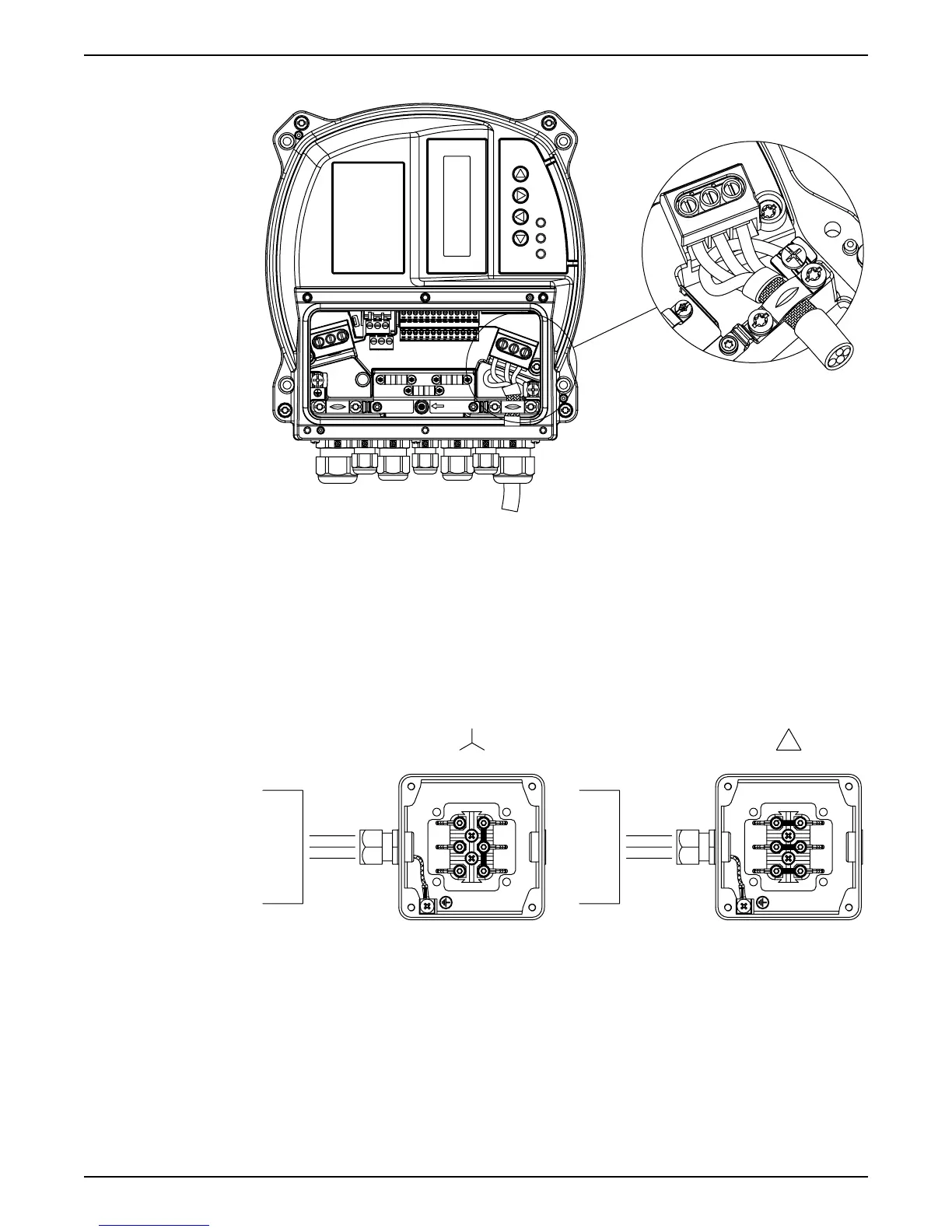
• Connect 3–phase motor wiring to terminals U, V, and W.
HVNG-IOM_MOTOR-SUPPLY_A_SC
U V W
L1/L L2 L3/N
RFI
SWITCH
U V W
• Ground the cable in accordance with grounding instructions provided
• Torque terminals in accordance with the informations provided.
• Follow motor manufacturer wiring requirements
• The connection of the motor cable depends on the type of motor and can be done in
star or delta connection: the right connection of the motor has to be selected as shown
on the motor label according to the output voltage of the Hydrovar.
• The connection of the motor cable shield can be done using a pigtail connected to a
PE screw (see image below), or by using a metallic cable gland in case of motor with
metallic conduit box connected to PE.
U
V
W
U
V
W
H
Y
D
R
O
V
A
R
H
Y
D
R
O
V
A
R
U
V
W
U
V
W
MOT_CONN_A-SC
6.6 Control terminals
Unscrew the dedicated 6 screws and remove the plastic cover of the Hydrovar, in order to
proceed wiring the control terminals, as described in the following paragraphs; for
reference, the wiring harness scheme is reported on the backside of the plastic cover too.
6 Electrical Installation
34 HVL 2.015-4.220 Installation, Operation, and Maintenance Manual