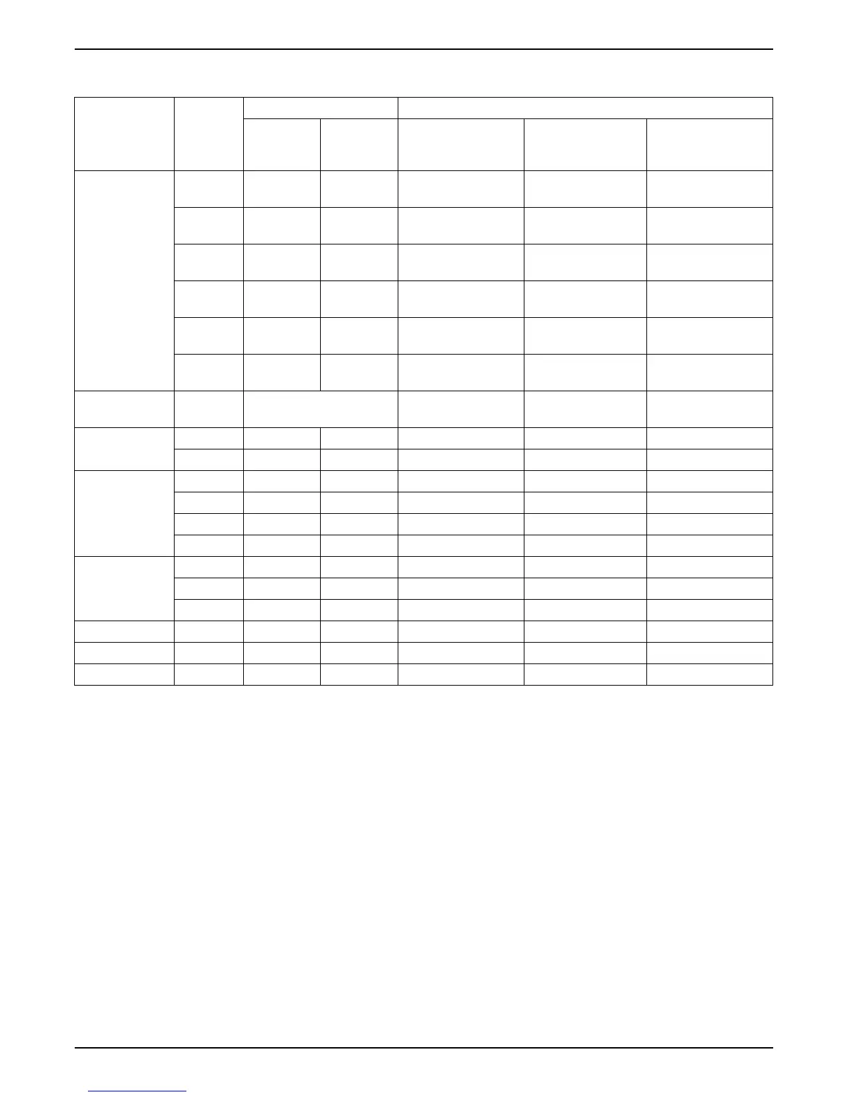
3.9 Included mounting components
Included
components
Cable outer diameter Model
(mm) inches HVL 2.015 ÷ 2.022 |
3.015 ÷ 3.022 | 4.015
÷ 4.040
HVL 2.030 ÷ 2.040 |
3.030 ÷ 3.055 | 4.055
÷ 4.110
HVL 3.075 ÷ 3.110 |
4.150 ÷ 4.220
Cable Gland(s) and
Lock Nut(s)
M12 3.5 ÷ 7.0 0.138 ÷
0.275
3 3 3
M16 5.0 ÷ 10.0 0.197 ÷
0.394
2 2 2
M20 7.0 ÷ 13.0 0.275 ÷
0.512
2
M25 10.0 ÷ 17.0 0.394 ÷
0.669
2
M32 13.0 ÷ 21.0 0.512 ÷
0.827
2
M40 19.0 ÷ 28.0 0.748 ÷
1.102
2
Entry Thread
Reducer
M40 ->
M32
2
Plug(s) for Cable
Gland(s)
M12 3 3 3
M16 2 2 2
Screws M5x30 4
M5x40 4
M6x40 4 4
M6x50 4 4
Spade
Connector(s) for PE
conductors
RF-U 4 2 2
BF-U 4 2 2
GF-U 4 2 2
Spares sealing ring 2
Centering pin 1 1 1
Mounting Clamps 4 4 4
For HVL 3.075 ÷ 3.110 or HVL 4.150 ÷ 4.220, if the cables outer diameter is incompatible
with the included cable glands, use the supplied Entry Thread Reducers (and spares
sealing rings).
3 Product Description
20 HVL 2.015-4.220 Installation, Operation, and Maintenance Manual