P415 SENSOR TYPE
4-20 mA
Actual Value Output Freq.
Left fct. Up fct. Down fct. Right fct.
Possible setting are:
Table 14: Selection of the sensor type and input terminal
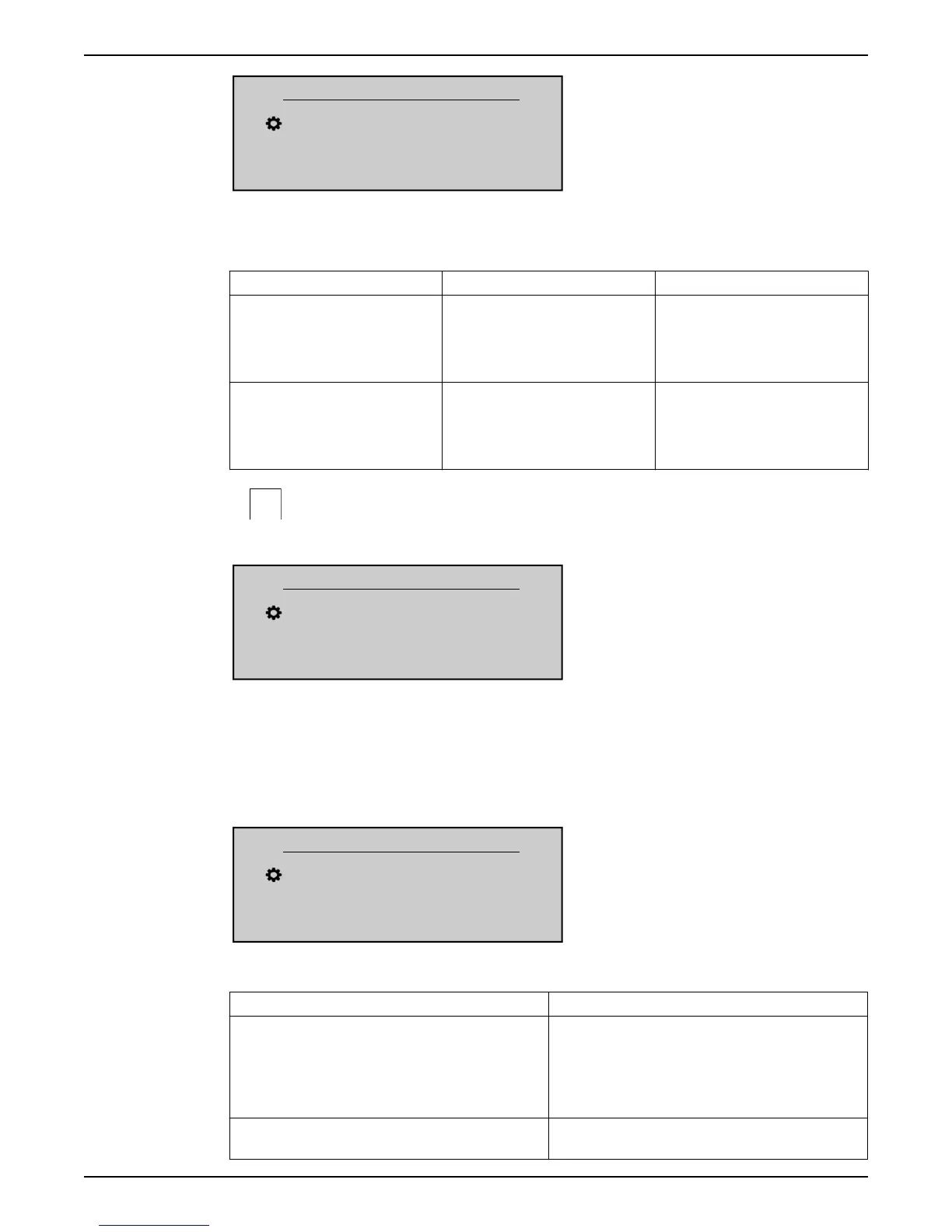
Setting Input Terminals Actual Value
• Analog I 4 - 20 mA
• Analog I 0- 20 mA
• X1/2:
Sensor 1
• X1/5:
Sensor 2
It is determined by a current signal
connected to the given input
terminal.
Analog U 0-10 V • X1/2:
Sensor 1
• X1/5:
Sensor 2
It is determined from a voltage signal
connected to the given input
terminal.
P420 SENSOR RANGE
Sets the end range value (20 mA or 10 V) of the connected sensor.
P420 SENSOR RANGE
20mA - 10.00bar
Actual Value Output Freq.
Left fct. Up fct. Down fct. Right fct.
In particular, the end range value (20mA or 10V) shall be always equal to the 100% of the
sensor range (i.e. for a 0.4bar differential pressure sensor, will be 20mA=0.4bar)
P425 SENSOR CURVE
Sets the mathematical function (curve) to determine the Actual Value based on the Sensor
signal.
P425 SENSOR CURVE
Linear
Actual Value Output Freq.
Left fct. Up fct. Down fct. Right fct.
Possible setting are:
Setting Application
Linear • Pressure control
• Differential Pressure control
• Level
• Temperature
• Flow control (inductive or mechanical)
Quadratic • Flow control (using an orifice plate with a differential
pressure sensor)
8 Programming
HVL 2.015-4.220 Installation, Operation, and Maintenance Manual 73