POWR
Power unit
5-45
6D93G11
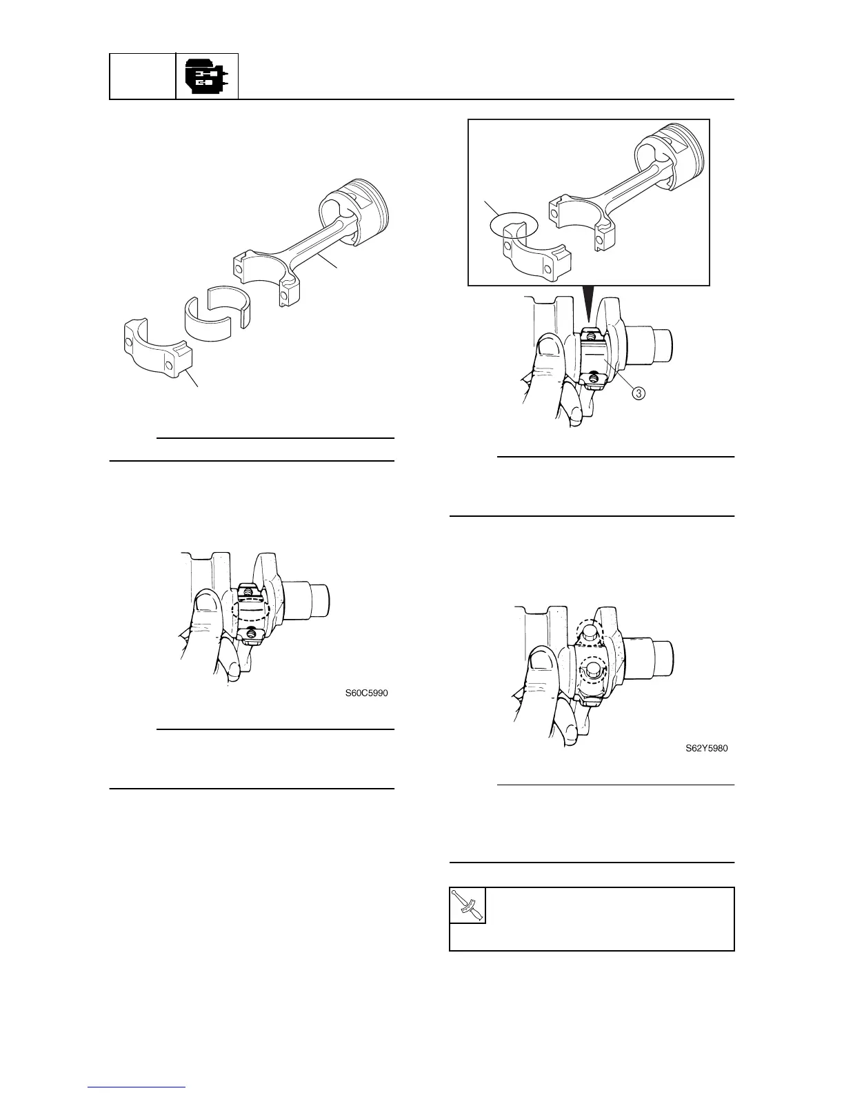
2. Install the upper bearing into the con-
necting rod
1
and the lower bearing into
the connecting rod cap
2
.
NOTE:
Install the bearings in their original positions.
3. Put a piece of Plastigauge (PG-1) onto
the crankpin, parallel to the crankshaft.
NOTE:
Be sure not to put the Plastigauge (PG-1)
over the oil hole in the crankpin of the crank-
shaft.
4. Install the connecting rod to the crankpin
3
.
NOTE:
Make sure that the large, flat side
a
on the
connecting rod faces towards the flywheel
magnet side of the crankshaft.
5. Tighten the connecting rod bolts to the
specified torques in two stages.
NOTE:
• Reuse the removed connecting rod bolts.
• Do not turn the connecting rod until the
crankpin oil clearance measurement has
been completed.
S60C5960
1
2