6D93G11
5-52
1
2
3
4
5
6
7
8
9
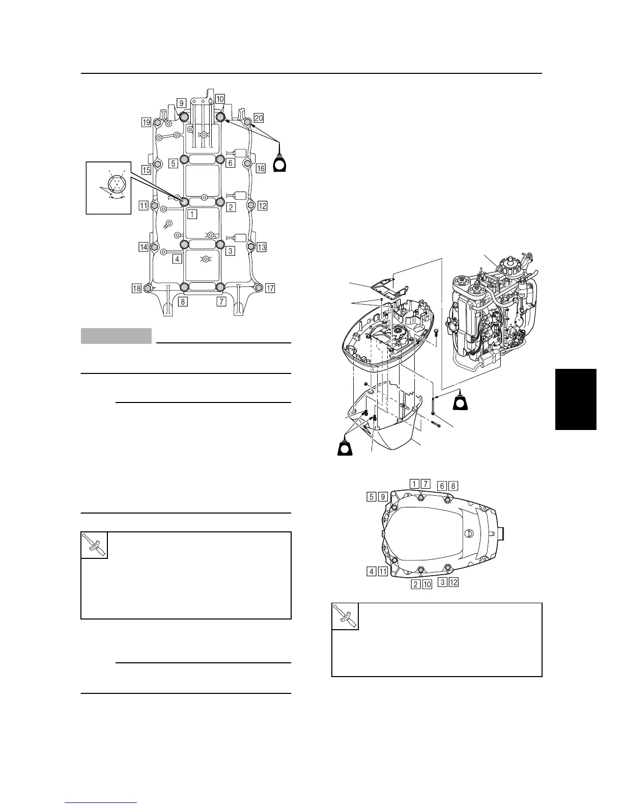
CAUTION:
The oil seals must be installed before
tightening the crankcase bolts.
NOTE:
• Tighten the M10 bolts to 19 N·m (1.9 kgf·m,
14.0 ft·lb) first, and then tighten the M8
bolts to 14 N·m (1.4 kgf·m, 10.3 ft·lb).
• Make a mark
d
on the M10 bolts and the
crankcase, and then tighten the bolts 60°
from the mark.
• Tighten the M8 bolts to 28 N·m (2.8 kgf·m,
20.7 ft·lb).
12. Install the cylinder head.
NOTE:
For cylinder head installation procedure, see
“Installing the cylinder head.”
13. Install all parts removed during disas-
sembly.
Installing the power unit
1. Clean the power unit mating surface, and
install the dowels
1
and a new gasket
2
.
2. Install the power unit
3
by installing bolts
4
and
5
, then tightening them to the
specified torques in two stages and in the
sequence shown.
3. Install the apron
6
.
4. Install the oil dipstick.
5. Connect the flushing hose, cooling water
pilot hose, and canister hose.
T
R
.
.
Crankcase bolt (M10):
1st: 19 N·m (1.9 kgf·m, 14.0 ft·lb)
2nd: 60°
Crankcase bolt (M8):
1st: 14 N·m (1.4 kgf·m, 10.3 ft·lb)
2nd: 28 N·m (2.8 kgf·m, 20.7 ft·lb)
S6D85680
60˚
d
E
Power unit mounting bolt
4
:
1st: 42 N·m (4.2 kgf·m, 31.0 ft·lb)
2nd: 42 N·m (4.2 kgf·m, 31.0 ft·lb)
Apron screw:
4 N·m (0.4 kgf·m, 3.0 ft·lb)
S6D85630
LT
572
LT
LT
572
LT
6
2
1
5
5
3
4
S6D85310
Cylinder block