6D93G11
5-46
1
2
3
4
5
6
7
8
9
6. Remove the connecting rod cap and
measure the width of the compressed
Plastigauge (PG-1) on each crankpin.
Replace the connecting rod bearing if out
of specification.
Selecting the connecting rod bearing
NOTE:
Use a metric gauge in this procedure.
1. When replacing the connecting rod bear-
ing, select the suitable bearing as fol-
lows.
2. Measure the connecting rod big end
inside diameter
a
.
NOTE:
Reuse the removed connecting rod bolts.
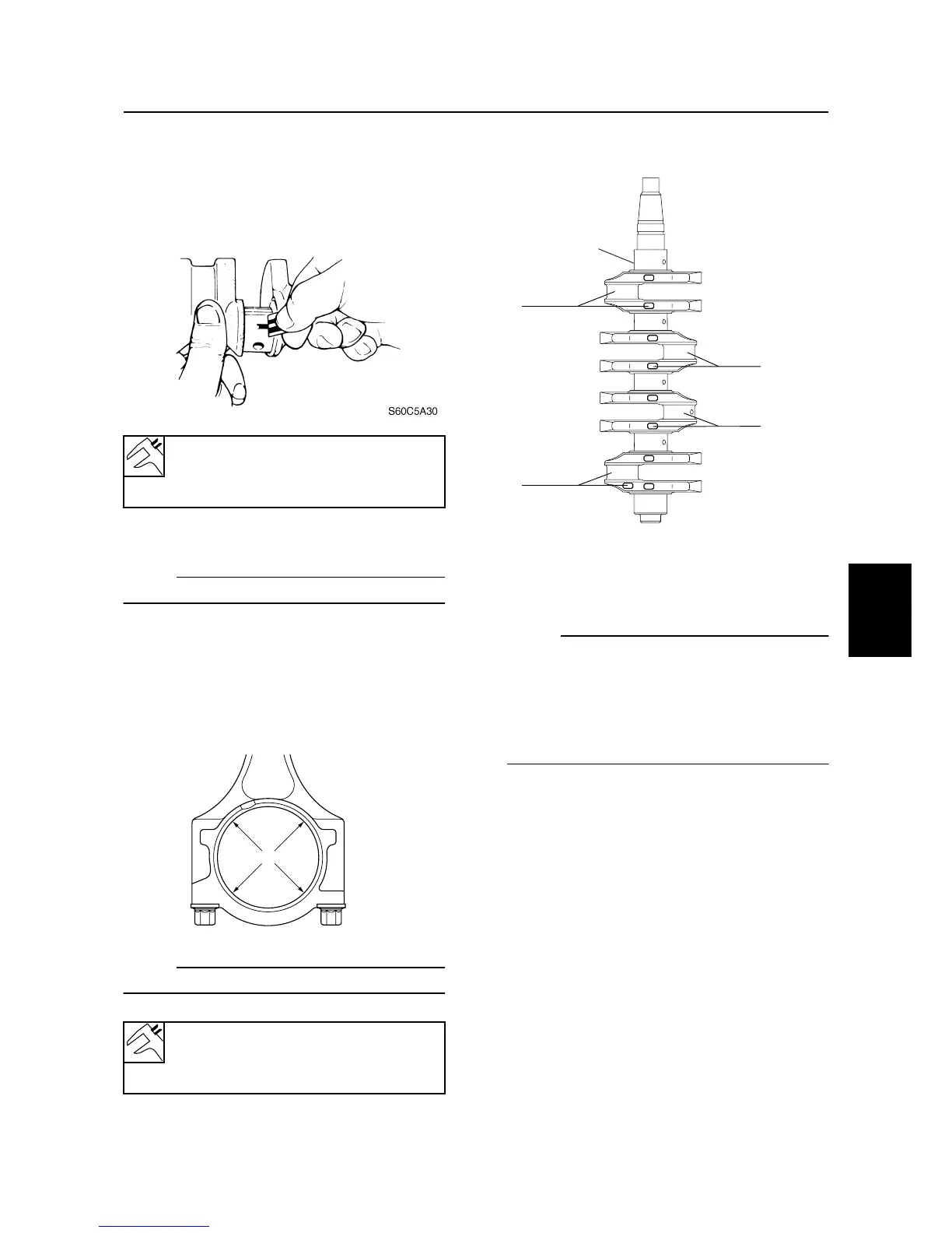
3. Check the crankpin mark on the crank-
shaft
1
.
4. Subtract the crankpin diameters (#1–#4)
from the connecting rod big end inside
diameters (#1–#4).
NOTE:
The crankpin diameters (#1–#4) can be
determined by the stamped value as
described below.
Crankpin diameter = 43.900 + (stamped
value/1,000)
Example: #1 = 92
→
43.992
Crankpin oil clearance:
0.024–0.044 mm
(0.0009–0.0017 in)
Connecting rod big end inside
diameter
a
:
47.025–47.045 mm
S60C5980
a
(#1)
(#2)
(#3)
S6D85670
(#4)
1
Cylinder block