LOWR
Lower unit
6-29
6D93G11
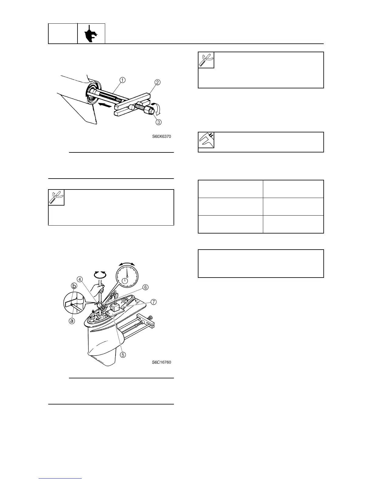
3. Install the special service tool so that it
pushes against the propeller shaft.
NOTE:
Tighten the center bolt while turning the drive
shaft until the drive shaft can no longer be
turned.
4. Install the backlash indicator onto the
drive shaft (20 mm [0.79 in] in diameter),
then the dial gauge onto the lower unit.
NOTE:
Install the dial gauge so that the plunger
a
contacts the mark
b
on the backlash indica-
tor.
5. Slowly turn the drive shaft clockwise and
counterclockwise and measure the back-
lash when the drive shaft stops in each
direction.
6. Add or remove shims if out of specifica-
tion.
M: Measurement
7. Remove the special service tools and
then install the water pump assembly.
Bearing housing puller claw L
1
:
90890-06502
Stopper guide plate
2
: 90890-06501
Center bolt
3
: 90890-06504
Backlash indicator
4
: 90890-06706
Magnet base plate
5
: 90890-07003
Dial gauge set
6
: 90890-01252
Magnetic base B
7
: 90890-06844
Forward gear backlash:
0.28–0.63 mm (0.0110–0.0248 in)
Forward gear
backlash
Shim thickness
Less than
0.28 mm (0.0110 in)
To be decreased by
(0.46 – M)
×
0.56
More than
0.63 mm (0.0248 in)
To be increased by
(M – 0.46)
×
0.56
Available shim thicknesses:
0.10, 0.12, 0.15, 0.18, 0.30, 0.40, and
0.50 mm