POWR
Power unit
5-11
6D93G11
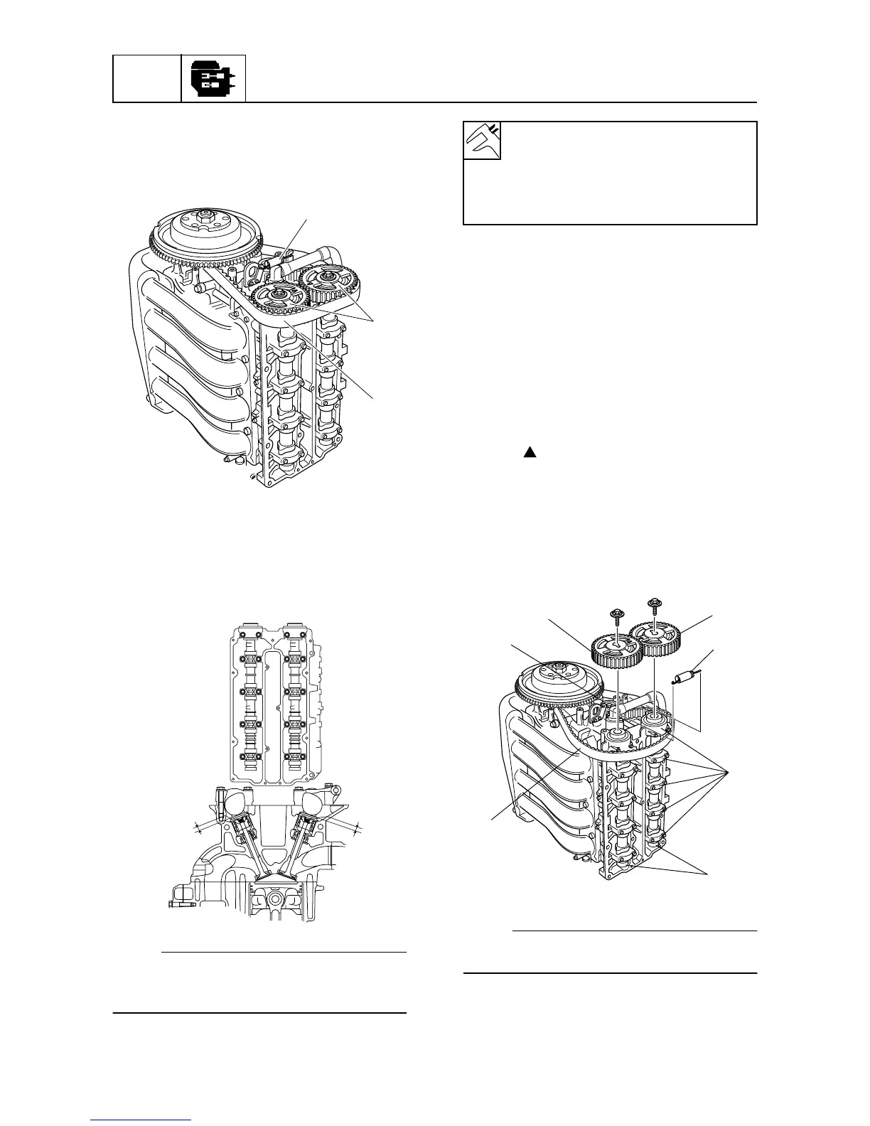
4. Install the driven sprockets
0
, timing belt
9
, and spring
8
, and then tighten the
tensioner bolt.
5. Check the intake valve clearance for cyl-
inders #1 and #2, and the exhaust valve
clearance for cylinders #1 and #3. Adjust
if out of specification.
NOTE:
• Check the valve clearance when the engine
is cold.
• Note the measurement.
6. Turn the flywheel magnet 360° clock-
wise.
7. Check the intake valve clearance for cyl-
inders #3 and #4, and the exhaust valve
clearance for cylinders #2 and #4. Adjust
if out of specification.
8. Turn the flywheel magnet clockwise and
align the “TDC” mark on the flywheel
magnet with the pointer, and check that
the “” marks on the driven sprockets
are aligned.
9. Loosen the tensioner bolt
7
, and then
remove the spring
8
, timing belt
9
,
driven sprockets
0
, camshaft caps
A
,
and camshafts
B
.
NOTE:
Do not mix the valve train parts. Keep them
organized in their proper groups.
10. Remove the valve lifters from the cylinder
head.
S6D85160
8
0
9
S6D85170
IN EX
#1
#2
#3
#4
f
e
Valve clearance (cold):
Intake
e:
0.20 ± 0.03 mm (0.008 ± 0.001 in)
Exhaust f:
0.34 ± 0.03 mm (0.013 ± 0.001 in)
S6D85180
B
A
0
0
7
9
8