69J1D11
5-52
1
2
3
4
5
6
7
8
9
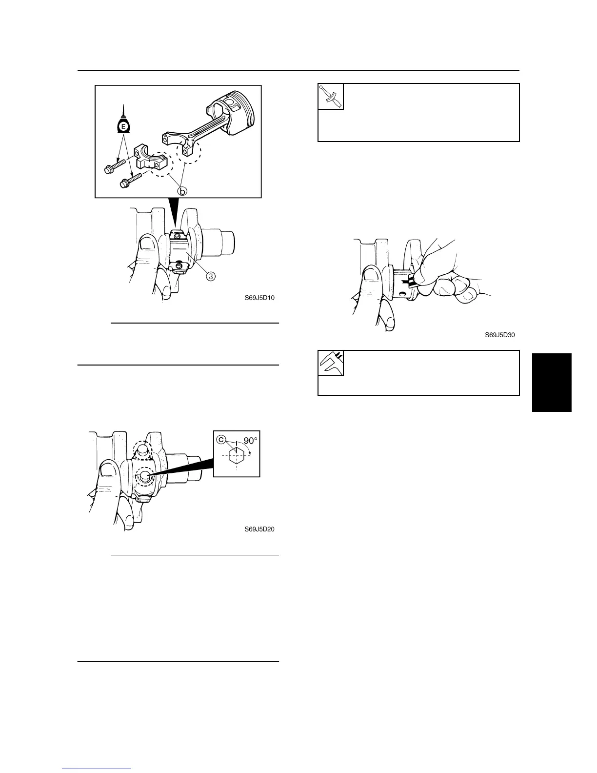
NOTE:
Align the marks
b
on the connecting rod cap
and connecting rod, which you made during
disassembly.
6. Tighten the connecting rod bolts to the
specified torques in three stages.
NOTE:
• Reuse the removed connecting rod bolts
when checking the oil clearance.
• Do not turn the connecting rod until the
crankpin oil clearance measurement has
been completed.
• Make a mark
c
on the connecting rod
bolts, connecting rod caps, and then tighten
the bolts 90° from the mark.
7. Remove the connecting rod cap and
measure the width of the compressed
Plastigauge (PG-1) on each crankpin.
Replace the connecting rod bearing if out
of specification.
Selecting the connecting rod bearing
1. When replacing the connecting rod bear-
ing, select the suitable bearing as fol-
lows.
2. Check the crankpin mark
a
on the
crankshaft.
Connecting rod bolt:
1st: 23 N·m (2.3 kgf·m, 17 ft·lb)
2nd: 48 N·m (4.8 kgf·m, 35 ft·lb)
3rd: 90°
Crankpin oil clearance:
0.035–0.071 mm
(0.0014–0.0028 in)
Cylinder block
 Loading...


