69J1D11
7-44
1
2
3
4
5
6
7
8
9
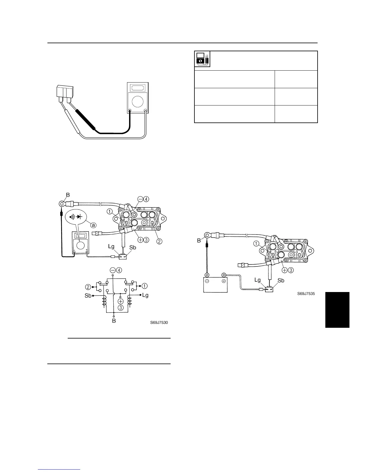
Checking the fuse
1. Check the fuse for continuity. Replace if
there is no continuity.
Checking the power trim and tilt
relay
1. Check the power trim and tilt relay for
continuity. Replace if out of specification.
NOTE:
Be sure to set the measurement range
a
shown in the illustration when checking for
continuity.
2. Connect the digital circuit tester between
power trim and tilt relay terminals
1
and
3
.
3. Connect the light green (Lg) lead to the
positive battery terminal and the black
(B) lead to the negative battery terminal
as shown.
4. Check for continuity between terminals
1
and
3
. Replace if there is no continu-
ity.
5. Connect the digital circuit tester between
power trim and tilt relay terminals
2
and
3
.
6. Connect the sky blue (Sb) lead to the
positive battery terminal and the black
(B) lead to the negative battery terminal
as shown.
7. Check for continuity between terminals
2
and
3
. Replace if there is no continu-
ity.
S69J7525
Power trim and tilt relay continuity
Sky blue (Sb) – Black (B)
Light green (Lg) – Black (B)
Continuity
Terminal
1
– Terminal
4
Terminal
2
– Terminal
4
Continuity
Terminal
1
– Terminal
3
Terminal
2
– Terminal
3
No continuity
Power trim and tilt electrical system
 Loading...


