13
RX-A4A
Nut (M9)
ナット (M9)
フック
フック
OPERATION (7) P.C.B.
C
Cover
カバー
LCD MODULE
LCDモジュール
OPERATION (6) P.C.B.
CB453
CB453
CB454
CB454
OPERATION (7) P.C.B.
FRONT PANEL ASSEMBLY
フロントパネルAss’y
Rear view
B
B
Hook
Hook
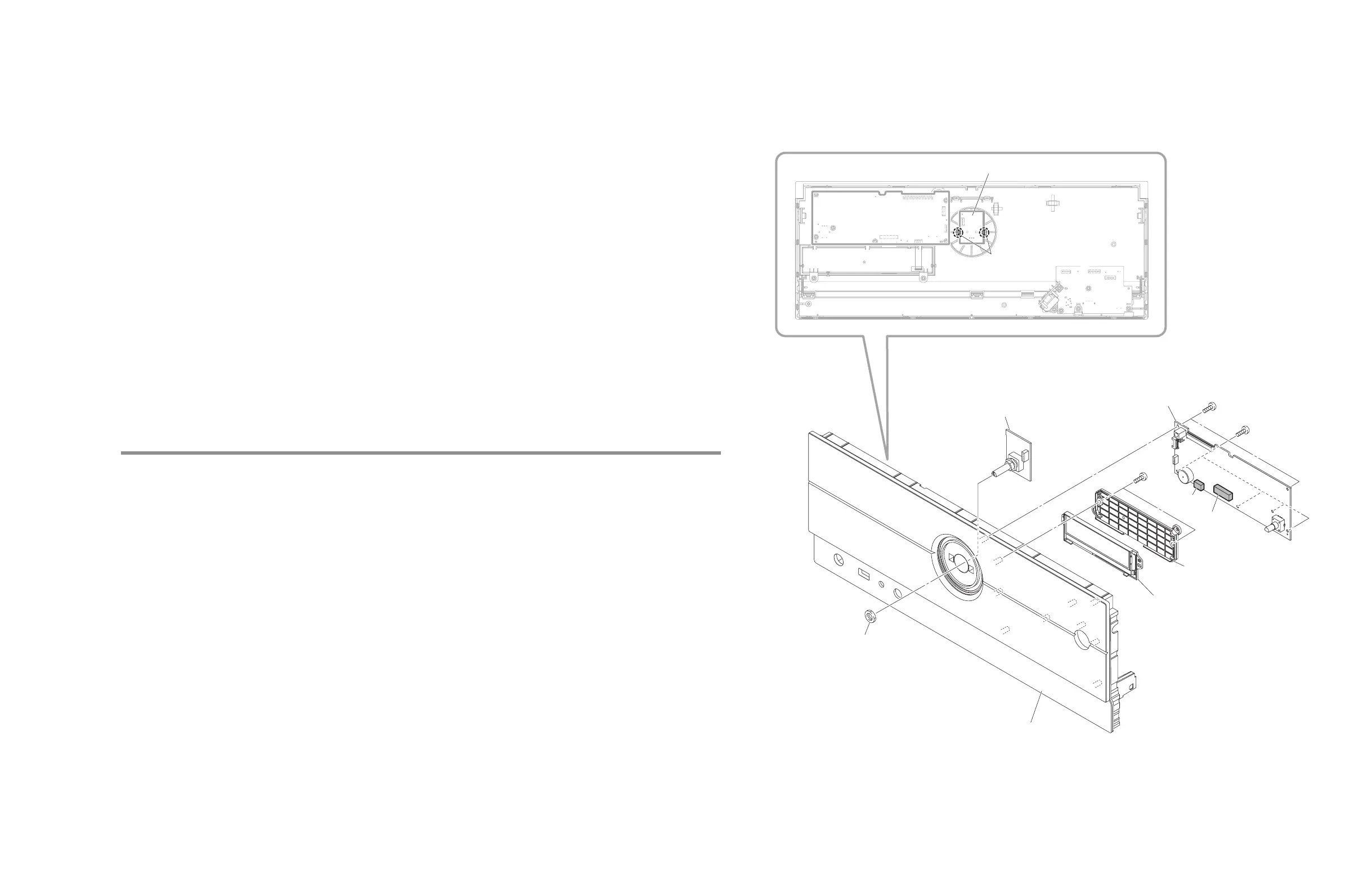
Fig. 4
3-2. OPERATION (6)、(7) P.C.B.、LCD モジュールの外し方 (Fig. 4)
フロントパネル Assʼy は下記対策のために、組み付けられた状態でサービスパーツとして供給されます。
• フロントパネルとウィンドウシートを両面テープで全面接着させるため
• フロント面のタッチセンサー感度の精度を確保するため
フロントパネル Assʼy の構成内容は下記のとおりです。
• フロントパネル、ウィンドウシート
• OPERATION (8) P.C.B.
• ディフューザシート、レンズ
他、両面テープなど
a. フロント面のナット(M9)1 個を外します。
b. フック 2 カ所を外し、OPERATION (7) P.C.B. を外します。
c.
l
のネジ 6 本を外します。
d. CB453、CB454 を外し、OPERATION (6) P.C.B. を外します。
e.
m
のネジ 2 本を外し、カバーを外します。
f. LCD モジュールを外します。
3-2. Removal of OPERATION (6), (7) P.C.B. and LCD MODULE (Fig. 4)
The FRONT PANEL ASSEMBLY is supplied as a service part assembled for the following purposes.
• To fasten together the FRONT PANEL and WINDOW SHEET surface-wide with double-sided tape
• To ensure the accuracy of the sensitivity of the front panel touch sensors
The FRONT PANEL ASSEMBLY is composed of the following.
• FRONT PANEL, WINDOW SHEET
• OPERATION (8) P.C.B.
• SHEET DIFFUSER, LENS
Others: Double-sided tape, etc.
a. Remove the Nut (M9) on the Front panel side.
b. Release hooks at 2locations, and then remove the OPERATION (7) P.C.B.
c. Remove 6 screws (
l
).
d. Remove 453 and CB454, and then remove the OPERATION (6) P.C.B.
e. Remove 2 screws (
m
), and then remove the cover.
f. Remove the LCD MODULE.
 Loading...