9
RX-A4A
n
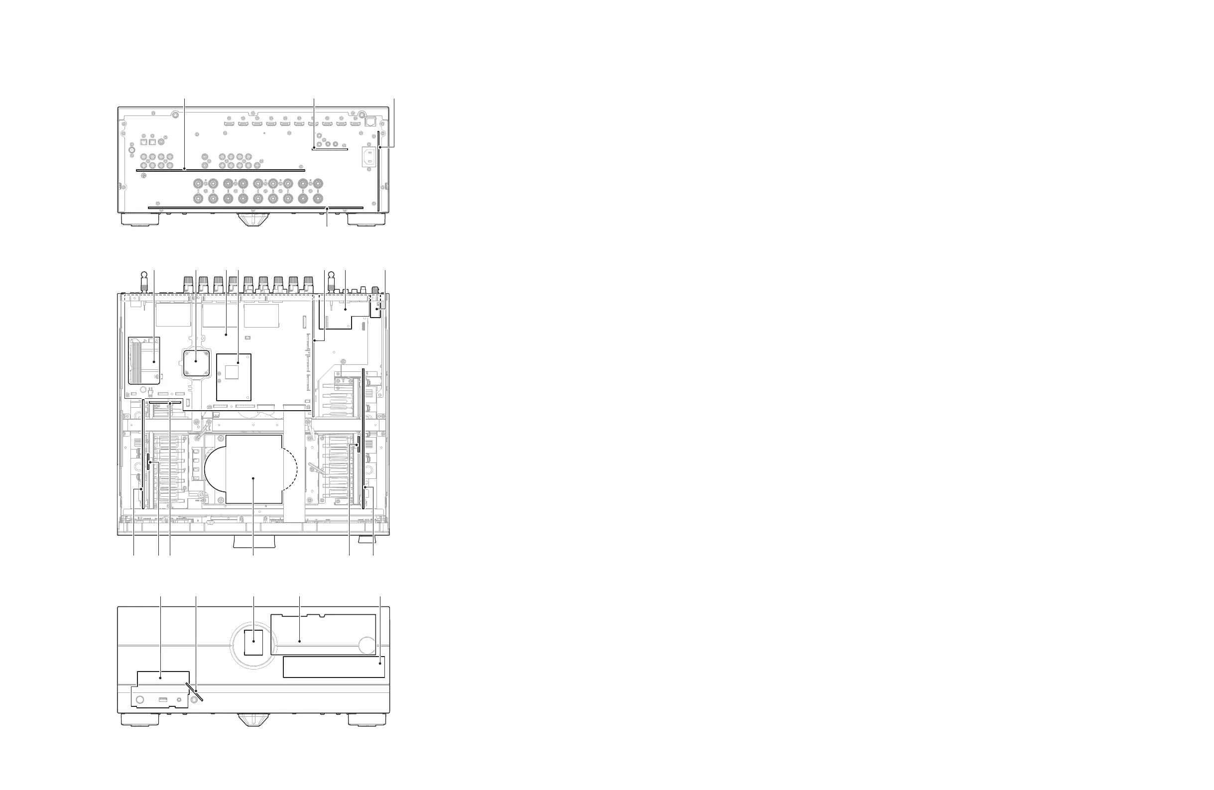
CIRCUIT BOARDS LAYOUT / ユニットレイアウト
1
6 7 8 j5
r ts u v
2
4
no mq lp
9 k
Rear view
Top view
Front view
a
FUNCTION (1) P.C.B.
b
OPERATION (2) P.C.B.
c
OPERATION (1) P.C.B.
d
AMPPOWER P.C.B.
e
Wireless Network Module
f
DC FAN MOTOR
g
DIGITAL P.C.B.
h
DSP P.C.B.
i
FUNCTION (2) P.C.B.
j
FUNCTION (3) P.C.B.
k
TUNER MODULE (J, U, C, R, T, K, L, V,
P, S models)
DAB MODULE (A, B, G, F models)
l
AMP (1) P.C.B.
m
AMP (3) P.C.B.
n
POWER TRANSFORMER
o
AMP (5) P.C.B.
p
AMP (4) P.C.B.
q
AMP (2) P.C.B.
r
OPERATION (4) P.C.B.
s
OPERATION (5) P.C.B.
t
OPERATION (7) P.C.B.
u
OPERATION (6) P.C.B.
v
OPERATION (8) P.C.B.
n
SERVICE PRECAUTIONS / サービス時の注意事項
注意:
DIGITAL P.C.B. または DIGITAL P.C.B. の IC90 を交換する
と、“Internal Error” が表示されて本機が正常に動作しなくな
ります。正常に動作させるために、モデル名、仕向け先、シ
リアル番号をバックアップ IC(EEPROM:DIGITAL P.C.B. の
IC90)へ書き込む必要があります。(詳しい手順は、関連す
るサービスニュース、または技術報告を参照してください。
もしくはヤマハのサービスセンターまでご連絡ください)。
安全対策
• この製品の内部には高電圧部分があり危険です。修理の際
は、絶縁性の手袋を使用するなどの安全対策を行ってくだ
さい。
• 下記のコンデンサには電源を OFF にした後も電荷が残り、
高電圧が維持されており危険です。
修理作業前に放電用抵抗(5 k Ω /10 W)を下記の各コン
デンサの端子間に接続して放電してください。
放電所用時間は各々約 30 秒間です。
OPERATION (1) P.C.B. の C4006
AMPPOWER P.C.B. の C3013、C1014、C3017、
C3023、C3024、C3029
「シート基板図」(66 ページ、76 ページ)を参照してく
ださい。
Note:
When the DIGITAL P.C.B. or IC90 on DIGITAL P.C.B. is
replaced, this unit will display “Internal Error” and will not
operate properly. The model name, destination and serial
number MUST be written to the backup IC (EEPROM: IC90
on DIGITAL P.C.B.) to have proper operation. (For detailed
procedure, refer to related Service News or Service Bulletin.
Or contact your local Yamaha representative.)
Safety measures
• Some internal parts in this product contain high voltages
and are dangerous. Be sure to take safety measures
during servicing, such as wearing insulating gloves.
• Note that the capacitors indicated below are dangerous
even after the power is turned off because an electric
charge remains and a high voltage continues to exist
there.
Before starting any repair work, connect a discharging
resistor (5 k-ohms/10 W) to the terminals of each capacitor
indicated below to discharge electricity.
The time required for discharging is about 30 seconds per
each.
C4006 on OPERATION (1) P.C.B.
C3013, C1014, C3017, C3023, C3024
and C3029 on AMPPOWER P.C.B.
Please refer to “CIRCUIT BOARDS” (P.66, P.76).