15
RX-A4A
Rear view
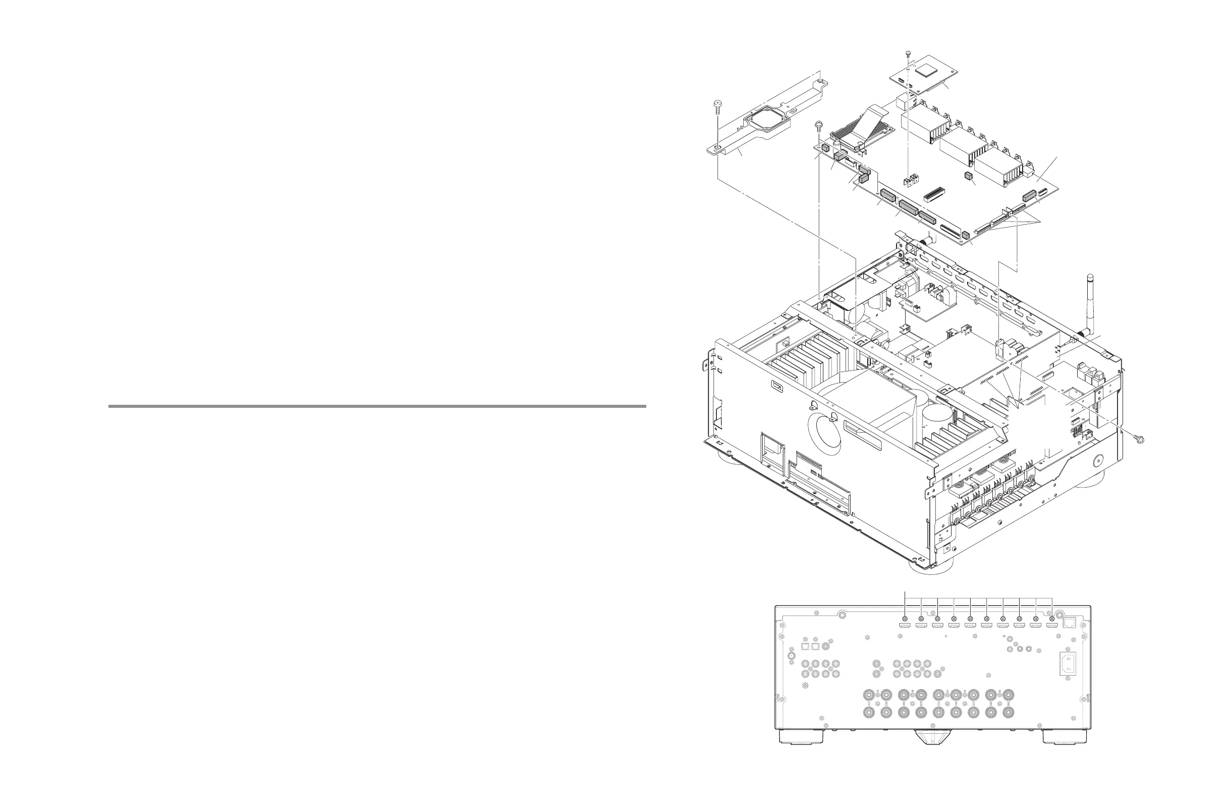
DIGITAL P.C.B.
DSP P.C.B.
FUNCTION (2) P.C.B.
G
FAN SUPPORT
FANサポート
E
H
H
F
CB84
CB84
CB122
CB122
CB121
CB121
CB80
CB80
CB83
CB83
CB82
CB82
CB81
CB81
CB85
CB85
CB23
CB23
CB134
CB134
Board-to-board
connector
基板対基板
コネクター
Board-to-board
connector
基板対基板
コネクター
Fig. 7
Fig. 8
5. FAN サポート、DSP P.C.B.、DIGITAL P.C.B. の外し方
a. CB23 を外します。 (Fig.7)
b.
o
のネジ 2 本を外し、FAN サポートを外します。 (Fig.7)
c.
p
のネジ 2 本を外し、DSP P.C.B. を外します。 (Fig.7)
d.
q
のネジ 10 本を外します。 (Fig.8)
e.
r
のネジ 4 本を外します。 (Fig.7)
f. CB80、CB81、CB82、CB83、CB84、CB85、CB121、CB122、CB134 を外します。 (Fig.7)
g. DIGITAL P.C.B. を外します。ただし、DIGITAL P.C.B. は FUNCTION (2) P.C.B. に基板対基板コネクターで直接接続されてい
ます。 (Fig.7)
※ 各基板は、基板対基板コネクターに対して垂直に外してください。基板対基板コネクターをこじ開けたり基板を斜めに外
したりしないでください。
5. Removal of FAN SUPPORT, DSP P.C.B. and DIGITAL P.C.B.
a. Disconnect CB23. (Fig.7)
b. Remove 2 screws (
o
), and then remode the FAN SUPPORT. (Fig.7)
c. Remove 2 screws (
p
), and then remode the DSP P.C.B. (Fig.7)
d. Remove 10 screws (
q
). (Fig.8)
e. Remove 4 screws (
r
). (Fig.7)
f. Disconnect CB80, CB81, CB82, CB83, CB84, CB85, CB121, CB122 and CB134. (Fig.7)
g. Remove the DIGITAL P.C.B. which is connected directly to the FUNCTION (2) P.C.B. with board-to-board connectors. (Fig.7)
* Remove each P.C.B. vertically to its board-to-board connector. Do not pry open the board-to-board connector or remove
the P.C.B. by tilting.



 To Next Page