16
RX-A4A
フック
フック
Hook
Hook
Rear view
FUNCTION (3) P.C.B.
FUNCTION (1) P.C.B.
AMP (2) P.C.B.
AMP (2) P.C.B.
FUNCTION (2) P.C.B.
L
L
CB605
CB605
CB201
CB201
CB240
CB240
Board-to-board
connector
基板対基板
コネクター
I J K
CB648
CB648
AMP (1) P.C.B.
AMP (1) P.C.B.
Fig. 9
Fig. 10
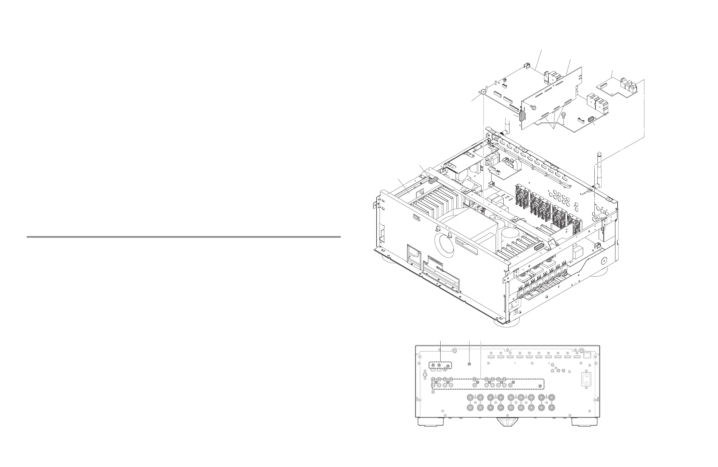
6. Removal of FUNCTION (1), (2) and (3) P.C.B.
a. Remove 3 screws (
s
). (Fig.10)
b. Remove the FUNCTION (3) P.C.B. (Fig.9)
c. Remove screw (
t
) and 7 screws (
u
). (Fig.10)
d. Disconnect CB201, CB240, CB605 and CB648. (Fig.9)
e. Remove 2 screws (
v
) and release 1 hook, and then remove the FUNCTION (1) P.C.B. and FUNCTION (2) P.C.B. together.
(Fig.9)
* FUNCTION (1) P.C.B. is connected directly to the FUNCTION (2) P.C.B. with board-to-board connectors.
Remove each P.C.B. vertically to its board-to-board connector. Do not pry open the board-to-board connector or remove
the P.C.B. by tilting.
6. FUNCTION (1)、(2)、(3) P.C.B. の外し方
a.
s
のネジ 3 本を外します。 (Fig.10)
b. FUNCTION (3) を外します。 (Fig.9)
c.
t
のネジ 1 本、
u
のネジ 7 本を外します。 (Fig.10)
d. CB201、CB240、CB605、CB648 を外します。 (Fig.9)
e.
v
のネジ 2 本、フック 1 ヶ所を外し、FUNCTION (1) を FUNCTION (2) P.C.B. と一緒に外します。 (Fig.9)
※ FUNCTION (1) P.C.B. は FUNCTION (2) P.C.B. に基板対基板コネクターで直接接続されています。
各基板は、基板対基板コネクターに対して垂直に外してください。基板対基板コネクターをこじ開けたり基板を斜めに外
したりしないでください。
 Loading...