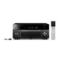
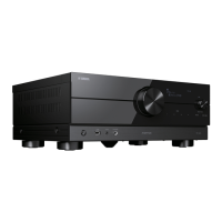
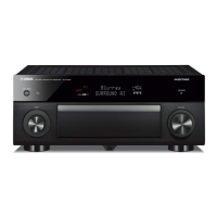
RX-A4A
36
N2. WIFI
無線 LAN アダプターに関連する機能を設定します。
N2-1–N2-10. WIFI ON JIG01–10
Wi-Fi 機能を「有効」にします。
(ESSID: JIG01~10)
MENU (CONNECT) キーで実行します。
N2-1
WIFI ON JIG01
N2-10
WIFI ON JIG10
・・・・・・・・・・・
N2-11. WIFI OFF
Wi-Fi 機能を「無効」にします。
ネットワークが初期設定になります。
MENU (CONNECT) キーで実行します。
N2-11
WIFI OFF
N2-12. WIFI MAC ADDRESS
無線 LAN アダプターの MAC アドレスが表示され
ます。
N2-12
ECF4514DCE7D
N2-13. WIFI RF TEST
RF 出力レベル簡易測定のための無変調出力をしま
す。
N2-13
WIFI RF TEST
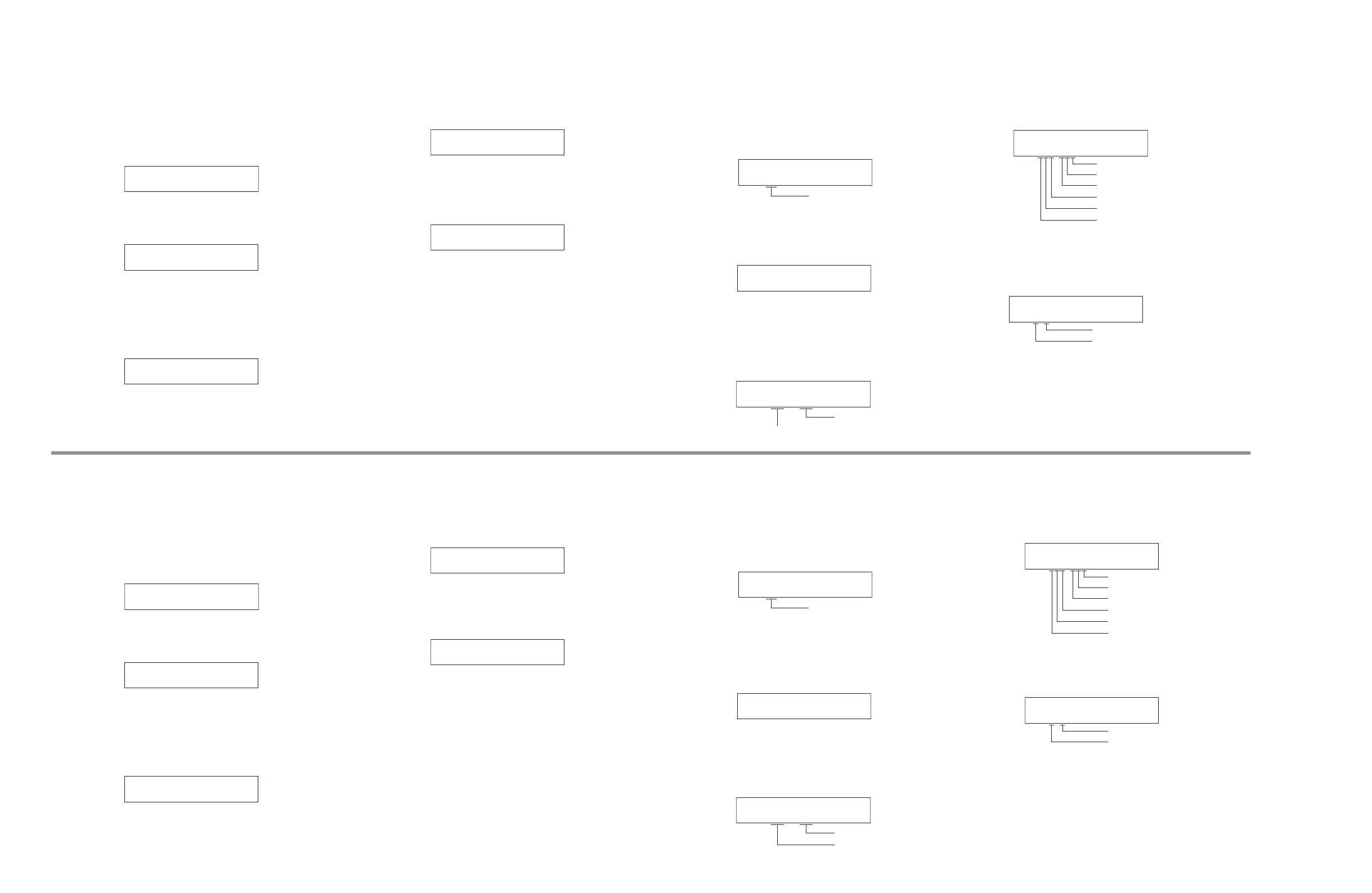
C1. ACCESS CHECK
DIGITAL P.C.B. 上の各デバイス間の通信とバスライン接
続をチェックします。
C1-1. ALL
サブメニュー C1-2 ~ C1-9 の総合判定結果が表示
されます。
C1-1
ALL:OK
OK: 不良検出なし
NG: 不良検出あり
--: チェック中
C1-2. BUS FLASH ROM
FLASH ROM(IC93)の読み出し/書き込みをチェッ
クします。
C1-2
BUS_FROM:OK
C1-3. BUS FPGA
マイコン(IC92)と FPGA GUI (IC54)/FPGA Audio
(IC155) 間の通信とバスライン接続をチェックしま
す 。( OK: 不良検出なし、NG: 不良検出あり)
FPGA Audio (IC155)
FPGA GUI (IC54)
C1-3
F-P B:OK,--,OK
C1-4. I2C
I2C(Inter integrated circuit)バスライン接続を
チェックします。 (0: OK, 1: NG)
C1-4
I2C:000-000:OK
チューナーの不良検出
タッチパネル (IC481) の不良検出
eARC (IC30) の不良検出
HDMI RTX (IC21) の不良検出
HDMI SW2 (IC2) の不良検出
HDMI SW1 (IC1) の不良検出
C1-5. I2C2
I2C(Inter integrated circuit)バスライン接続を
チェックします。 (0: OK, 1: NG)
C1-5
I2C:0-0-:OK
ZONE2 DSP (IC130) の不良検出
ESS DAC1 (IC136) の不良検出
N2. WIFI
This menu is used to set functions related to wireless LAN
adaptor.
N2-1–N2-10. WIFI ON JIG01–10
Set Wi-Fi function to “Enable“. (ESSID: JIG01–10)
Touch the MENU (CONNECT) key to set.
N2-1
WIFI ON JIG01
N2-10
WIFI ON JIG10
・・・・・・・・・・・
N2-11. WIFI OFF
Set Wi-Fi function to “Disable“.
Network settings will be the default setting.
Touch the MENU (CONNECT) key to set.
N2-11
WIFI OFF
N2-12. WIFI MAC ADDRESS
MAC address of the wireless LAN adaptor is
displayed.
N2-12
ECF4514DCE7D
N2-13. WIFI RF TEST
Make unbiased output for simple measurement of
the RF output level.
N2-13
WIFI RF TEST
C1. ACCESS CHECK
This menu is used to check the communication and bus
line connection between devices on DIGITAL P.C.B.
C1-1. ALL
The total detection result of sub-menus from C1-2
to C1-9 is displayed.
C1-1
ALL:OK
OK: No error detected
NG: An error is detected
--: Checking
C1-2. BUS FLASH ROM
FLASH ROM (IC93)ʼs reading/writing are checked.
C1-2
BUS_FROM:OK
C1-3. BUS FPGA
Communication and bus line connection between
microprocessor (IC92) and FPGA GUI (IC54)/FPGA
Audio (IC155) are checked. (OK: No error detected,
NG: An error is detected)
FPGA Audio (IC155)
FPGA GUI (IC54)
C1-3
F-P B:OK,--,OK
C1-4. I2C
The I2C (Inter integrated circuit) bus line
connection is checked. (0: OK, 1: NG)
C1-4
I2C:000-000:OK
Error detection of Tuner
Error detection of Touch panel (IC481)
Error detection of eARC (IC30)
Error detection of HDMI RTX (IC21)
Error detection of HDMI SW2 (IC2)
Error detection of HDMI SW1 (IC1)
C1-5. I2C2
The I2C (Inter integrated circuit) bus line
connection is checked.
C1-5
I2C:0-0-:OK
Error detection of ZONE2 DSP (IC130)
Error detection of ESS DAC1 (IC136)