19
RX-A4A
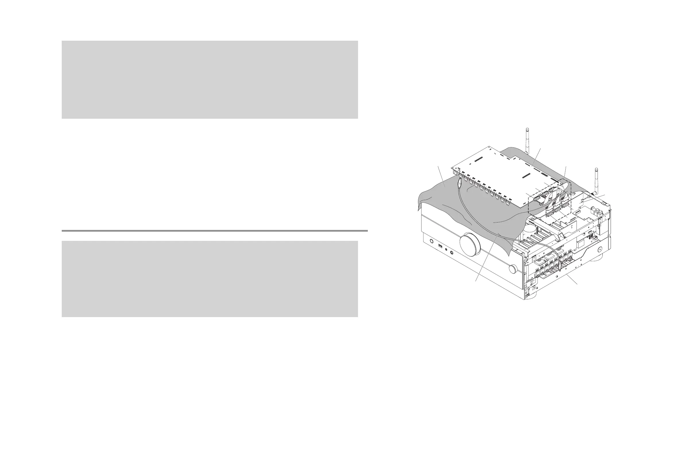
When checking the DIGITAL P.C.B. (Fig. 14)
• Put the rubber sheet and cloth over this unit, and place the DIGITAL P.C.B. on them.
• Connect CB8 on DIGITAL P.C.B. to the chassis with a ground lead.
• Reconnect all cables (connectors) that have been disconnected. Be sure to use the P.C.B. CHECKING JIG (Part No.
ZF906400 to connect between the following connectors.
CB123 on DIGITAL P.C.B. – CB646 on FUNCTION (6) P.C.B.
CB124 on DIGITAL P.C.B. – CB642 on FUNCTION (6) P.C.B.
CB125 on DIGITAL P.C.B. – CB304 on FUNCTION (6) P.C.B.
* When connecting the flexible flat cable, be careful with polarity.
DIGITAL P.C.B. をチェックする場合 (Fig. 14)
• 本機の上にゴムシートと布を敷き、その上に DIGITAL P.C.B. を置きます。
• DIGITAL P.C.B. の CB8 のアースをリード線でシャーシに接続してください。
• 外したケーブル(コネクター)をすべて接続します。ただし下記のコネクター間を接続するには P.C.B. チェック用ジグ(部
品番号 : ZF906400)を使用してください。
DIGITAL P.C.B. の CB123 – FUNCTION (2) P.C.B. の CB646
DIGITAL P.C.B. の CB124 – FUNCTION (2) P.C.B. の CB642
DIGITAL P.C.B. の CB125 – FUNCTION (2) P.C.B. の CB644
※ フラットケーブルを接続する際、極性に注意してください。
アース線
Ground lead
シャーシ
Chassis
DIGITAL P.C.B.
ゴムシートと布
Rubber sheet and cloth
FUNCTION (2) P.C.B.
CB124
CB642
CB642
P. C.B. CHECKING JIG
P.C.B. チェック用ジグ
CB125
CB123
CB644
CB644
CB646
CB646
Fig. 14
 Loading...