EasyManua.ls Logo

Yamaha XVS250 2001 - Page 38

Yamaha XVS250 2001
332 pages
Print Icon
To Next Page IconTo Next Page
To Previous Page IconTo Previous Page
Loading...
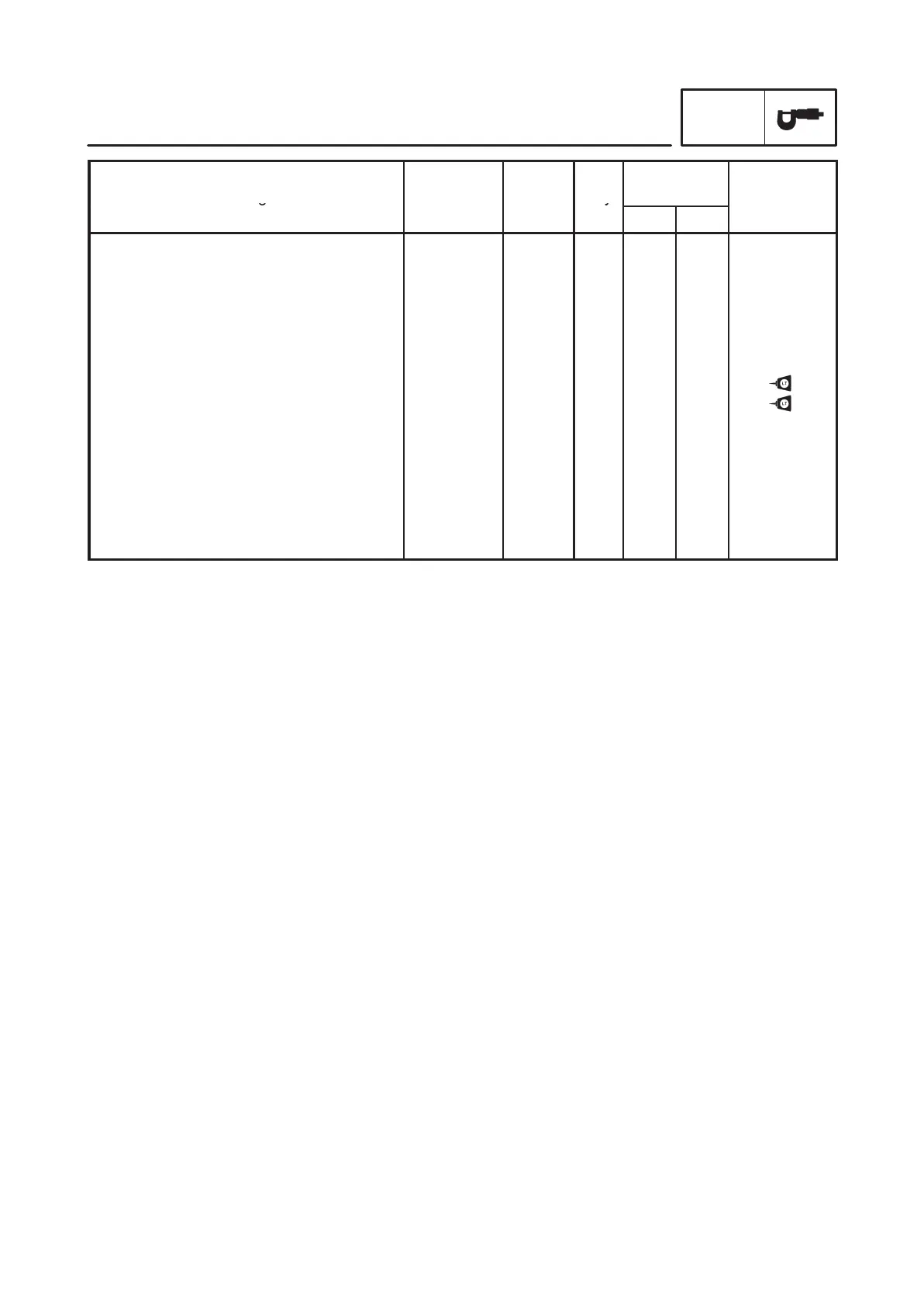
2-16
MAINTENANCE SPECIFICATIONS
SPEC
Part to be ti
g
htened Part name
Thread
size
Q’ty
Tightening
torque
Remarks
g
size
y
Nm mkg
Push lever axle
Drive sprocket
Shift drum segment
Shift arm
Shift pedal adjuster
Neutral switch
Stater coil
Pickup coil
Starter motor
Air induction case cover
Air induction case and bracket
Air induction case and frame
Air filter case and bracket
Air cutoff valve and bracket
Pipe and cylinder head
Screw
Nut
Screw
Bolt
Nut
Screw
Screw
Bolt
Screw
Nut
Bolt
Bolt
Bolt
Clamp
M8
M16
M5
M6
M8
M10
M6
M5
M6
M5
M6
M6
M6
M5
M6
1
1
1
1
2
1
3
2
2
4
3
2
3
3
2
12
60
3.8
8
10
20
7
5
10
1.3
5
5
5
3.8
2
1.2
6.0
0.38
0.8
1.0
2.0
0.7
0.5
1.0
0.13
0.5
0.5
0.5
0.38
0.2
1 of 2 has
LH thread

Table of Contents