6.4 Alarm Detection
Note: Digital operator display text is represented in the tables below using standard font for both LCD displays and LED displays. When using
the standard LED operator, however, display text will appear in 7-segment LED (ex: “
”). When the LED fault display differs from the
LCD display, the LED display text will be shown in parentheses under the LCD display text.
u
Alarm Codes, Causes, and Possible Solutions
Alarms are drive protection functions that do not necessarily cause the drive to stop. After removing the cause of an alarm,
the drive will return to its previous status before the alarm occurred.
When an alarm has been triggered, the ALM light on the digital operator display blinks and the alarm code display flashes. If
a multi-function output is set for an alarm (H2-oo = 10), that output terminal will be triggered.
Note:
If a multi-function output is set to close when an alarm occurs (H2-oo = 10), it will also close when maintenance periods are reached,
triggering alarms LT-1 through LT-4 (triggered only if H2-oo = 2F).
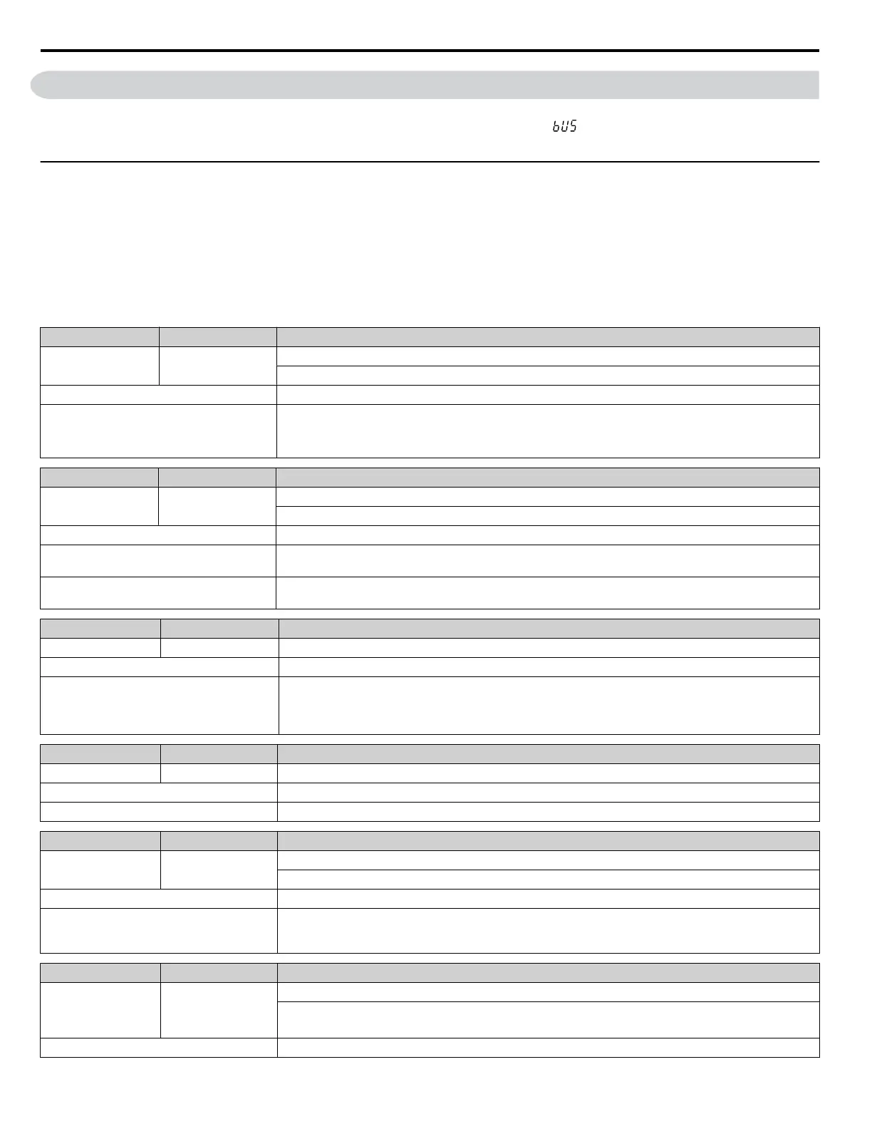
Table 6.3 Alarm Codes, Causes, and Possible Solutions
LED Display LCD Display Minor Fault Name
AEr
AEr
Station Address Setting Error (CC-Link, CANopen, MECHATROLINK)
Option card node address is outside the acceptable setting range.
Cause Possible Solution
Station number is set outside the possible
setting range.
• Set parameter F6-10 to the proper value if a CC-Link option card is used
• Set parameter F6-20 to the proper value if a MECHATROLINK option card is used.
• Set parameter F6-35 to the proper value if a CANopen option card is used.
LED Display LCD Display Minor Fault Name
AfbL
AnalogFB Lost
Switched to Net
Analog Feedback Lost
Analog feedback has not been detected and the network PID feedback signal is now used.
Cause Possible Solution
Defective or broken analog input source.
Confirm that the PID feedback source is installed and working properly. If there is no feedback source,
set P9-02 to 3 so the drive will read the network PID feedback from another drive.
H3-0o is not set to B (PID Feedback)
Set H3-0o to B if the analog input source is to be used for PID feedback.
Set P9-02 to 3 if the drive does not have an analog PID feedback source.
LED Display LCD Display Minor Fault Name
AJA
Anti-Jam Active
Anti-Jam Alarm
Cause Possible Solution
The drive is attempting to clear debris from
the impeller. This is only effective when
P7-01, Anti-jam Operation is set to 1
(enabled).
• Alarm will clear when function is complete.
• Drive response to this condition is controlled by P7-01, Anti-jam Operation Selection.
LED Display LCD Display Minor Fault Name
BAT
bAT
Digital Operator Battery Voltage Low
Cause Possible Solution
The digital operator battery is low Replace the digital operator battery.
LED Display LCD Display Minor Fault Name
bb
bb
Baseblock
Drive output interrupted as indicated by an external baseblock signal.
Cause Possible Solution
External baseblock signal was entered via one
of the multi-function input terminals
(S1 to S7).
Check external sequence and baseblock signal input timing.
LED Display LCD Display Minor Fault Name
bv5
bUS
Option Communication Error
• The connection was lost after initial communication was established.
• Assign a Run command frequency reference to the option.
Cause Possible Solution
6.4 Alarm Detection
268
YASKAWA TOEP YAIQPM 03B YASKAWA AC Drive - iQpump Micro User Manual

 Loading...


