3.7 Control Circuit Wiring
u
Control Circuit Terminal Block Functions
Drive parameters determine which functions apply to the multi-function digital inputs (S1 to S7), multi-function digital outputs
(MA, MB), multi-function pulse inputs and outputs (RP, MP) and multi-function photocoupler outputs (P1, P2). The default
is called out next to each terminal in
Figure 3.1.
WARNING! Sudden Movement Hazard. Always check the operation and wiring of control circuits after being wired. Operating a drive with
untested control circuits could result in death or serious injury.
WARNING! Confirm the drive I/O signals and external sequence before starting test run. Setting parameter A1-06 may change the I/O
terminal function automatically from the factory setting. Failure to comply may result in death or serious injury.
n
Input Terminals
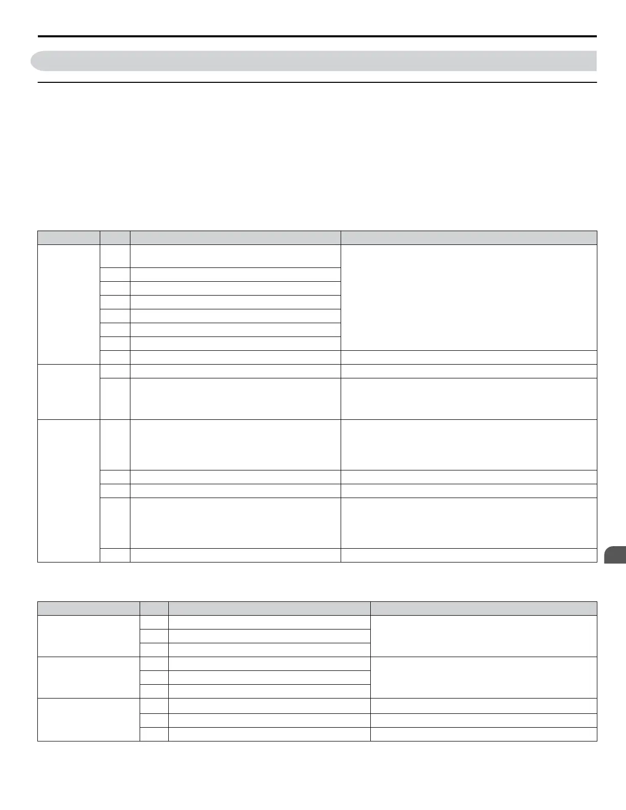
Table 3.8 Control Circuit Input Terminals
Type No. Terminal Name (Function) Function (Signal Level) Default Setting
Multi-Function
Digital Inputs
S1
Multi-function input 1 (Closed: Forward run, Open:
Stop)
Photocoupler
24 Vdc, 8 mA
Note: Drive preset to sinking mode. When using source mode, set
DIP switch S3 to allow for a 24 Vdc (±10%) external power supply.
Refer to Sinking/Sourcing Mode Switch on page 59 for details.
S2 Multi-function input 2 (Not used/Through mode)
S3 Multi-function input 3 (External pump fault (N.O.)
S4 Multi-function input 4 (Fault reset)
S5 Multi-function input 5 (Multi-step speed reference 1)
S6 Multi-function input 6 (HAND Mode)
S7 Multi-function input 7 (HAND Mode 2)
SC Multi-function input common (Control common) Sequence common
Safe Disable
Input
HC Power supply for safe disable input +24 Vdc (max 10 mA allowed)
H1 Safe disable input
Open: Output disabled
Closed: Normal operation
Note: Disconnect wire jumper between HC and H1 when using the
safe disable input. The wire length should not exceed 30 m.
Main
Frequency
Reference
Input
RP Multi-function pulse train input (frequency reference)
Response frequency: 0.5 to 32 kHz
(Duty Cycle: 30 to 70%)
(High level voltage: 3.5 to 13.2 Vdc)
(Low level voltage: 0.0 to 0.8 Vdc)
(input impedance: 3 kΩ)
+V Analog input power supply +10.5 Vdc (max allowable current 20 mA)
A1 Multi-function analog input 1 (frequency reference) Input voltage 0 to +10 Vdc (20 kΩ) resolution 1/1000
A2 Multi-function analog input 2 (frequency reference)
Input voltage or input current (Selected by DIP switch S1 and H3-09)
0 to +10 Vdc (20 kΩ),
Resolution: 1/1000
4 to 20 mA (250 Ω) or 0 to 20 mA (250 Ω),
Resolution: 1/500
AC Frequency reference common 0 Vdc
n
Output Terminals
Table 3.9 Control Circuit Output Terminals
Type No. Terminal Name (Function) Function (Signal Level) Default Setting
Multi-Function Digital
Output
<1>
MA N.O. (Fault)
Digital output
30 Vdc, 10 mA to 1 A; 250 Vac, 10 mA to 1 A
Minimum load: 5 Vdc, 10 mA (reference value)
MB N.C. (Fault)
MC Digital output common
Multi-Function
Photocoupler Output
P1 Photocoupler output 1 (During run)
Photocoupler output 48 Vdc, 2 to 50 mA
<2>
P2 Photocoupler output 2 (Fault)
PC Photocoupler output common
Monitor Output
MP Pulse train output (Output frequency)
32 kHz (max)
<3>
<4>
AM Analog monitor output 0 to 10 Vdc (2 mA or less) Resolution: 1/1000
AC Monitor common 0 V
<1> Do not assign functions to digital relay outputs that involve frequent switching. This may shorten relay performance life. Switching life is estimated
at 200,000 times (assumes 1 A, resistive load).
3.7 Control Circuit Wiring
YASKAWA TOEP YAIQPM 03B YASKAWA AC Drive - iQpump Micro User Manual
55
3
Electrical Installation

 Loading...


