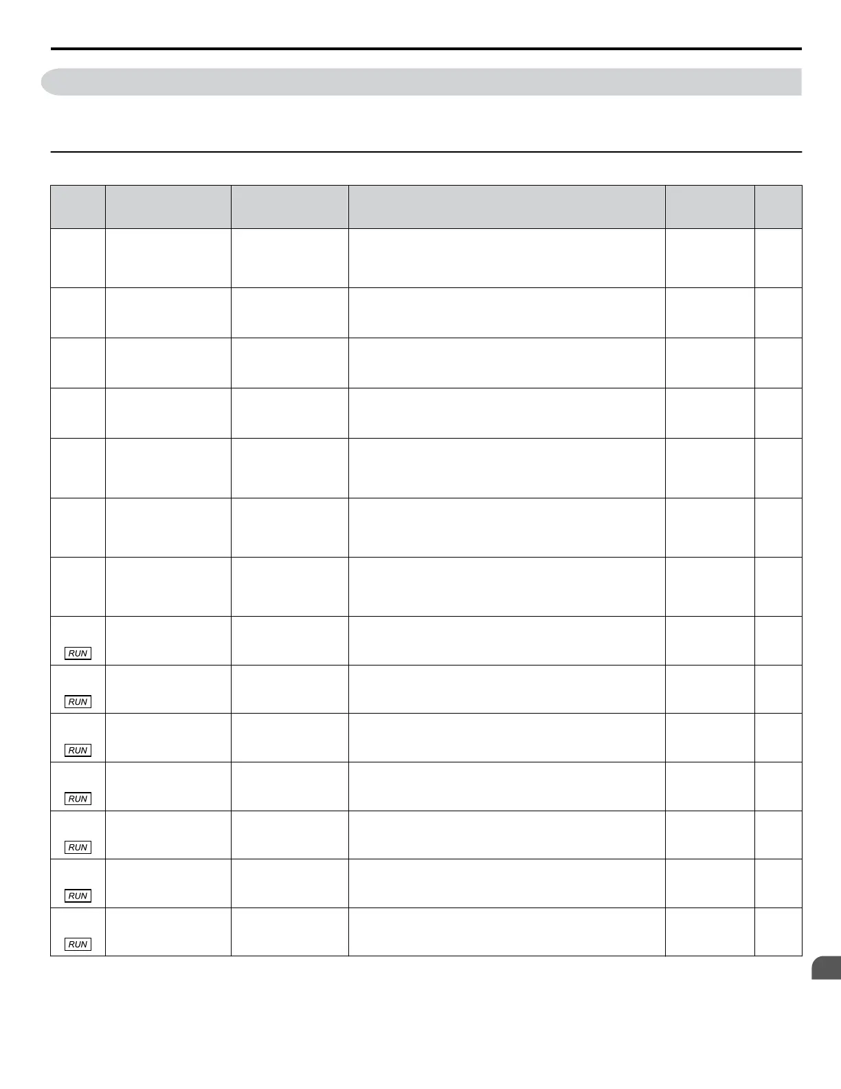
B.8 H Parameters: Multi-Function Terminals
H parameters assign functions to the multi-function input and output terminals.
Note: Cycle power to the drive to enable MEMOBUS/Modbus settings.
u
H1: Multi-Function Digital Inputs
No.
(Addr.
Hex)
Name LCD Display Description Values Page
H1-01
(0438)
Multi-Function Digital
Input Terminal S1
Function Selection
Term S1 Func Sel
Assigns a function to the multi-function digital inputs.
Refer to pages
336 to 339 for descriptions of setting values.
Note: Set unused terminals to F.
Default: 40 (F)
<1>
Min.: 2
Max.: B0
163
H1-02
(0439)
Multi-Function Digital
Input Terminal S2
Function Selection
Term S2 Func Sel
Assigns a function to the multi-function digital inputs.
Refer to pages 336 to 339 for descriptions of setting values.
Note: Set unused terminals to F.
Default: F
Min.: 2
Max.: B0
163
H1-03
(0400)
Multi-Function Digital
Input Terminal S3
Function Selection
Term S3 Func Sel
Assigns a function to the multi-function digital inputs.
Refer to pages 336 to 339 for descriptions of setting values.
Note: Set unused terminals to F.
Default: 26
Min.: 0
Max.: B0
163
H1-04
(0401)
Multi-Function Digital
Input Terminal S4
Function Selection
Term S4 Func Sel
Assigns a function to the multi-function digital inputs.
Refer to pages 336 to 339 for descriptions of setting values.
Note: Set unused terminals to F.
Default: 14
Min.: 0
Max.: B0
163
H1-05
(0402)
Multi-Function Digital
Input Terminal S5
Function Selection
Term S5 Func Sel
Assigns a function to the multi-function digital inputs.
Refer to pages 336 to 339 for descriptions of setting values.
Note: Set unused terminals to F.
Default: 8D (0)
<1>
Min.: 0
Max.: B0
163
H1-06
(0403)
Multi-Function Digital
Input Terminal S6
Function Selection
Term S6 Func Sel
Assigns a function to the multi-function digital inputs.
Refer to pages 336 to 339 for descriptions of setting values.
Note: Set unused terminals to F.
Default: 80 (3)
<1>
Min.: 0
Max.: B0
163
H1-07
(0404)
Multi-Function Digital
Input Terminal S7
Function Selection
Term S7 Func Sel
Assigns a function to the multi-function digital inputs.
Refer to pages 336 to 339 for descriptions of setting values.
Note: Set unused terminals to F.
Default: 81 (4)
<1>
Min.: 0
Max.: B0
163
H1-21
(02D7)
External Fault 1 Delay
Time
EF1 Delay Time
Sets the amount of time delay applied to the EF1 fault.
(20 ≤ H1-01 ≤ 2F)
Default: 0.00 s
Min.: 0.00
Max.: 300.00
167
H1-22
(02D8)
External Fault 2 Delay
Time
EF2 Delay Time
Sets the amount of time delay applied to the EF2 fault.
(20 ≤ H1-02 ≤ 2F)
Default: 0.00 s
Min.: 0.00
Max.: 300.00
167
H1-23
(02D9)
External Fault 3 Delay
Time
EF3 Delay Time
Sets the amount of time delay applied to the EF3 fault.
(20 ≤ H1-03 ≤ 2F)
Default: 0.00 s
Min.: 0.00
Max.: 300.00
167
H1-24
(02DA)
External Fault 4 Delay
Time
EF4 Delay Time
Sets the amount of time delay applied to the EF4 fault.
(20 ≤ H1-04 ≤ 2F)
Default: 0.00 s
Min.: 0.00
Max.: 300.00
167
H1-25
(02DB)
External Fault 5 Delay
Time
EF5 Delay Time
Sets the amount of time delay applied to the EF5 fault.
(20 ≤ H1-05 ≤ 2F)
Default: 0.00 s
Min.: 0.00
Max.: 300.00
167
H1-26
(02DC)
External Fault 6 Delay
Time
EF6 Delay Time
Sets the amount of time delay applied to the EF6 fault.
(20 ≤ H1-06 ≤ 2F)
Default: 0.00 s
Min.: 0.00
Max.: 300.00
167
H1-27
(02DD)
External Fault 7 Delay
Time
EF7 Delay Time
Sets the amount of time delay applied to the EF7 fault.
(20 ≤ H1-07 ≤ 2F)
Default: 0.00 s
Min.: 0.00
Max.: 300.00
167
<1> Value in parenthesis is the default setting when a 3-Wire initialization is performed (A1-03 = 3330).
B.8 H Parameters: Multi-Function Terminals
YASKAWA TOEP YAIQPM 03B YASKAWA AC Drive - iQpump Micro User Manual
335
B
Parameter List

 Loading...


