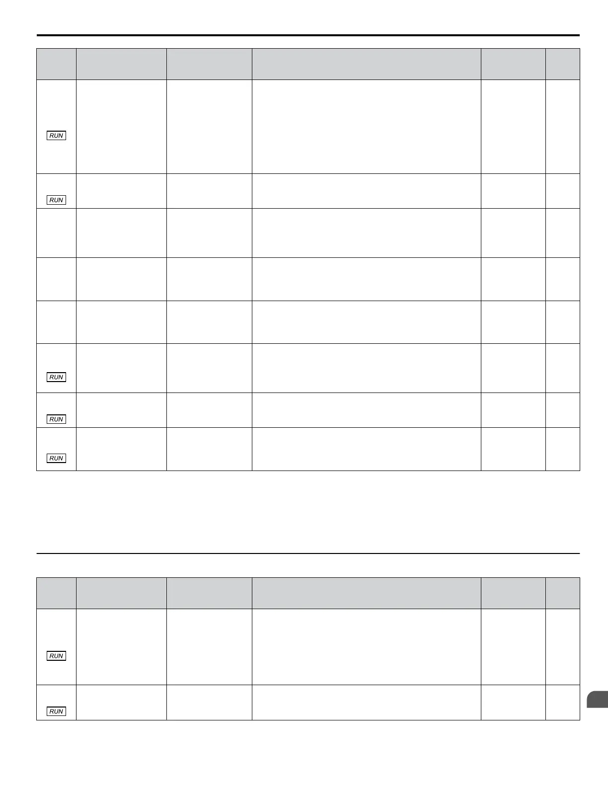
No.
(Addr.
Hex)
Name LCD Display Description Values Page
P2-10
(0C6D)
Sleep Mode: Cycling
Protection
Cycle Protection
Sets the maximum number of cycles that are allowed within the
time specified in P2-11 before tripping the PoC “Pump Over
Cycle” fault.
One cycle is defined when the drive transfers from normal
operation in AUTO Mode to Sleep Mode.
This function is active when the drive is running during AUTO
Mode. When P1-01 is set to 3 (MEMOBUS network), the
function is active when there is only one drive running on the
network.
Setting this parameter to 0 disables the function.
Default: 0
Min.: 0
Max.: 10
231
P2-11
(0C6E)
Sleep Mode: Maximum
Cycling Protection
Time
Max. Cycle Time
Sets the maximum time allowed between cycles. When no
cycling occurs within the programmed time, the drive will
decrease the internal cycle register.
Default: 300 s
Min.: 0
Max.: 3600
231
P2-12
(0C6F)
Over Cycling Mode
Over Cycle Mode
0: Disabled
1: Alarm Only
2: Fault
3: Auto SP Comp.
0: Disabled
1: Alarm
2: Fault
3: Auto SP Compensation
Default: 0
Range: 0 to 3
231
P2-13
(0C70)
Setpoint Compensation Setpoint Comp.
Allows for the software to automatically compensate the
setpoint in the event of excessive cycling.
Default: 0.0 PSI
<3>
Min.: 0.0
Max.: 6000.0
231
P2-14
(0C71)
Maximum Setpoint
Compensation
Max. SP Comp.
Sets the maximum allowed setpoint compensation for over-
cycling function.
Default: 0.0 PSI
<3>
Min.: 0.0
Max.: 6000.0
231
P2-23
(0C7A)
Anti-No-Flow
Bandwidth
ANF Bandwidth
Sets the amount of PID error bandwidth used to detect the Anti-
No-Flow condition.
Avoid setting this parameter value too high, as operation may
become unstable.
Setting this parameter to 0.00 will disable the function.
Default: 0.40%
Min.: 0.00
Max.: 2.00
231
P2-24
(0C7B)
Anti-No-Flow
Detection Time
ANF Det. Time
Sets the time delay before the drive starts the increased
deceleration rate after Anti-No-Flow is detected.
Default: 10.0 s
Min.: 1.0
Max.: 60.0
231
P2-25
(0C7C)
Anti-No-Flow Release
Level
ANF Release Lvl
Sets the amount below the setpoint which the feedback must
drop to disengage the Anti-No-Flow and return to normal PID
operation.
Default: 3.0 PSI
<3>
Min.: 0.0
Max.: 100.0
232
<1> Display units vary depending on the setting for P2-01, Sleep Level Type. When P2-01 is set to 0, the display units are “Hz”; setting 1 is “A”; setting
2 is P1-02 Selection; setting 3 is “RPM”.
<2> Display units vary depending on the setting for P2-01, Sleep Level Type. When P2-01 is set to 0, 1, or 2, the display units are “Hz”; setting 3 is
“RPM”.
<3> Unit is determined by P1-02, System Units; scaling is determined by P1-03, Feedback Device Scaling; resolution is determined by b5-39, PID
System Units Display Digits.
u
P4: Pump Advanced
No.
(Addr.
Hex)
Name LCD Display Description Values Page
P4-01
(0CFA)
Pre-Charge Level Pre-Charge Level
Runs the drive at the frequency set in P4-02.
The drive will exit Pre-charge when one of the following
conditions occurs:
• The feedback level rises above the level set in P4-01
• The pre-charge time set in P4-03 expires
• The low water digital input is deactivated (#8F) (if
programmed)
Default: 0.0 PSI
<1>
Min.: 0.0
Max.: 6000.0
229
P4-02
(0CFB)
Pre-Charge Frequency Pre-Charge Freq.
Sets the frequency reference used when the Pre-Charge function
is active.
Default: 0.0 Hz
Min.: 0.0
Max.: [E1-04]
229
B.12 P: Pump Parameters
YASKAWA TOEP YAIQPM 03B YASKAWA AC Drive - iQpump Micro User Manual
359
B
Parameter List

 Loading...


