6-2
170904-1CD
HW1482870
6 Allowable Load for Wrist Axis and Wrist Flange
6.2 Wrist Flange
MPL80
II
6.2 Wrist Flange
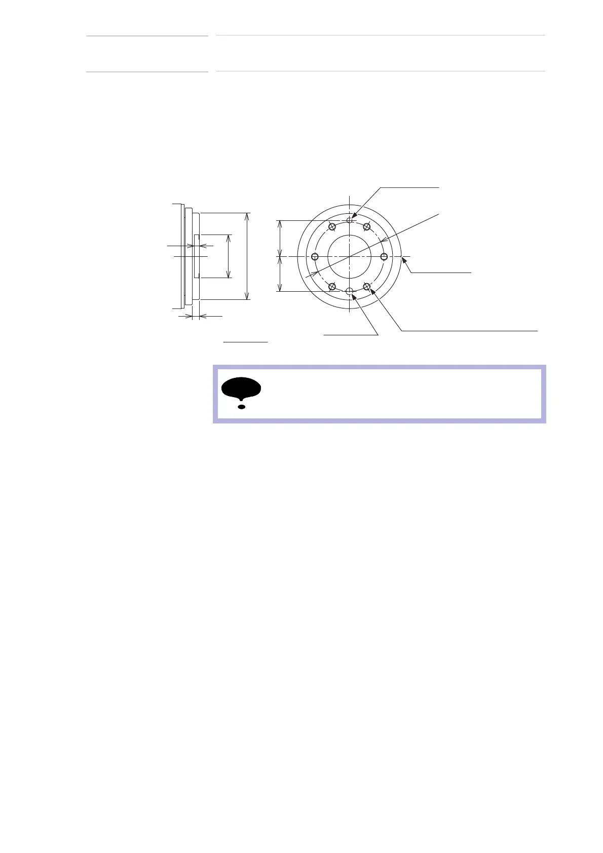
The wrist flange dimensions are shown in Fig. 6-2 “Wrist Flange”. In order
to see the alignment marks, it is recommended that the attachment be
mounted inside the fitting. Fitting depth of inside and outside fittings must
be 5 mm or less.
Fig. 6-2: Wrist Flange
Unit: mm
axis
Tapped hole M8
8 dia
Alignment mark
6 dia.
+0.012
0
50 dia.
0
-0.025
(depth: 10mm)
(depth:14 mm) (pitch:1.25) (6 holes)
(depth: 14mm)
+0.015
0
100 dia.
0
-0.022
P.C.D.80
4240
6
8
Wash off anti-corrosive paint (yellow) on the wrist flange
surface with thinner or light oil before mounting the tools.
 Loading...