7-2
170904-1CD
HW1482870
7 System Application
7.2 Internal User I/O Wiring Harness and Air Line
MPL80
II
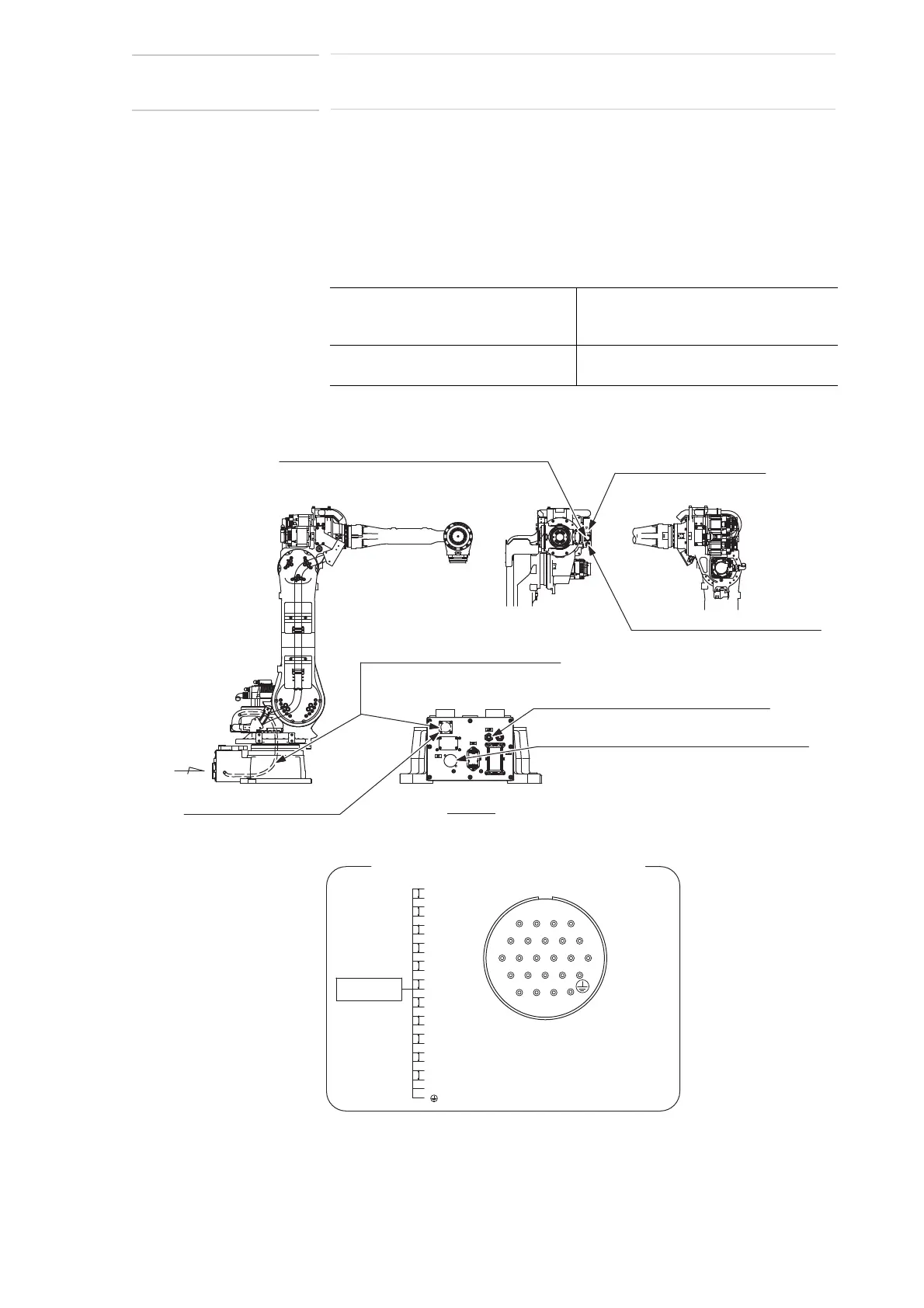
7.2 Internal User I/O Wiring Harness and Air Line
Internal user I/O wiring harness (0.5 mm
2
x 23 wires), and an air line are
incorporated in the manipulator for the drive of peripheral device mounted
on the upper arm as shown in Fig. 7-2 “Connectors for Internal User I/O
Wiring Harness and Air Line”.
The connector pins 1 to 23 are assigned as shown in Fig. 7-2. Wiring
must be performed by users.
Fig. 7-2: Connectors for Internal User I/O Wiring Harness and Air Line
The same numbered pins (1 to 23) of the two connectors are connected
with a single lead wire of 0.5 mm
2
.
The allowable current for internal user
I/O wiring harness
5.1 A or less for each wire
(The total current value for pins 1 to 23
must be 34.5 A or less.)
The maximum pressure for the air line 490 kPa (5 kgf/cm
2
) or less
(The air line inside diameter: 8.0 mm.)
A
Exhaust port
Tapped hole PT3/8 with pipe plug
Connector for Internal User I/O Wiring Harness
Pins used
Internal user I/O wiring harness :
0.5 mm
2
, 23 lead wires
8
4
9
65
1
7
23
14
19
20
15
17
11 12
18
13
21 22 23
10
16
P
P
P
P
P
P
P
P
P
P
P
1
6
5
3
4
2
7
8
9
10
15
14
13
12
11
20
19
17
18
16
22
23
21
Air inlet Tapped hole PT3/8 with pipe plug
Connector for internal user I/O wiringharness:
JL05-2A24-28SC (socket connector with a cap)
Prepare pin connector JL05-6A24-28P.
Connector for internal user I/O wiringharness:
JL05-2A24-28PC (socket connector with a cap)
Prepare pin connector JL05-6A24-28S.
Tube for field bus cable (inside dia.:12)
(inside of the manipulator base)
View A
Tapped hole M4x3 (4 holes)
(pitch: 0.7) (depth: 3)
Tapped hole M4x3 (4 holes)
(pitch: 0.7) (depth: 3)
 Loading...