2-12
166006-1CD
166006-1CD
2 Installation
2.3 Positioner Installation
RM2-755/1255SL
Positioner
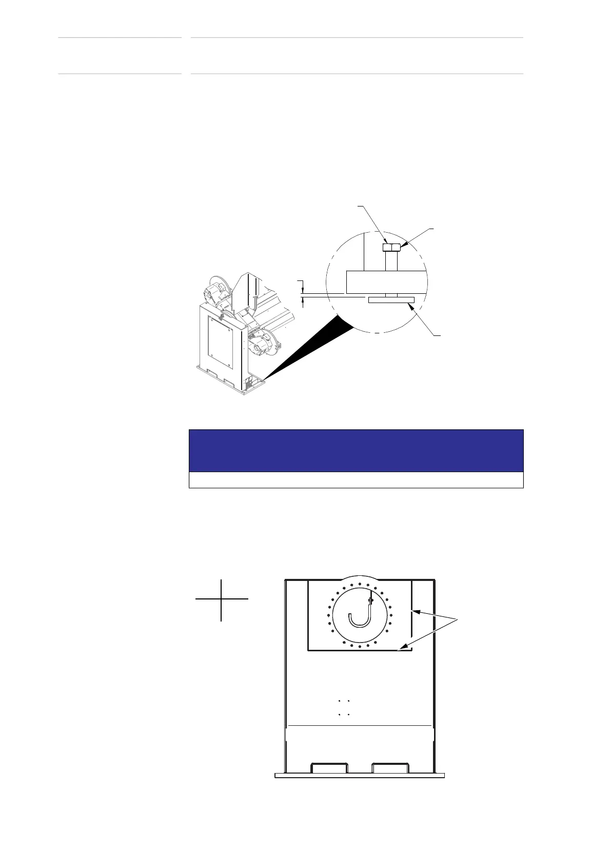
2.3.4.1 Setting Headstock
1. Place leveling bolt plates under each M20 leveling bolt so that the
leveling bolts do not rest on the concrete.
• There should be approximately 6.35mm between the top of the
leveling bolt plate and the underside of the headstock. See Fig. 2-6
as a reference only.
Fig. 2-6: Headstock Installation on Floor.
2. Place a machinists' level on the front of the machined surface of the
Headstock (without the overhead rail attachment if supplied).
Fig. 2-7: Headstock Machined Surface
NOTICE
This elevation is just a starting point, and is not a final requirement.
SET HEIGHT OF HEADSTOCK HOUSING
BY ADJUSTING LEVELING BOLTS
6.35mm
LEVELING
BOLT PLATE
M20 LEVELING
BOLT
x-axis
y-axis
Machined
Surface
 Loading...