5.1 Wiring Main Circuit
5-5
5
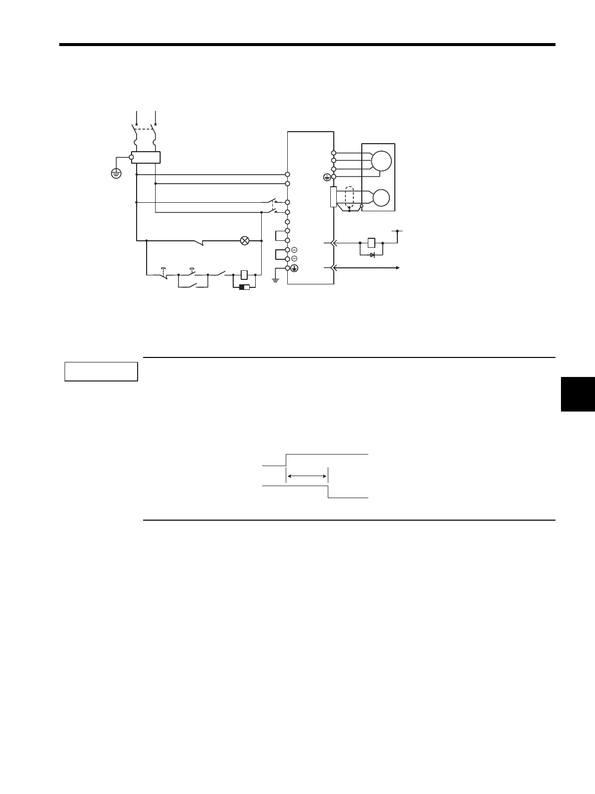
(3) 750 W, Single-phase 200V
Note: Terminal L3 is not used for the single-phase 200 V, 750W SERVOPACKs. Do not connect.
Designing a Power ON Sequence
Note the following points when designing the power ON sequence.
• Design the power ON sequence so that main circuit power is turned OFF when a servo alarm signal is output.
(See the circuit figure above.)
• The ALM signal is output for approximately two seconds when the power is turned ON. Take this into con-
sideration when designing the power ON sequence. The ALM signal actuates the alarm detection relay 1Ry
to stop main circuit power supply to the SERVOPACK.
• Select the power supply specifications for the parts in accordance with the input power supply.
SERVOPACK
SGDS-08A72A
OFF ON
(For servo
alarm
display)
Main
power
supply
Main
power
supply
L1
L1C
PG
U
V
W
M
0 V24
1Ry
ALM+
ALM−
31
32
1D
1KM
1Ry
1KM
1PRT
1Ry
1KM
L2
L3
L2C
CN1
1QF
R T
1PL
FIL
+24V
A
B
C
D
B2
B3
1
2
: Indicator lamp
: Surge protector
: Flywheel diode
1PL
1PRT
1D
1QF
FIL
1KM
1Ry
: Molded-case circuit breaker
: Noise filter
: Magnetic contactor
: Relay
IMPORTANT
Power supply
Servo alarm (ALM)
output signal
2.0 s max.
SIEPS80000025.book 5 ページ 2004年10月25日 月曜日 午前11時57分