3.6 Dimensional Drawings of SERVOPACK Model SGDS-72
3-19
3
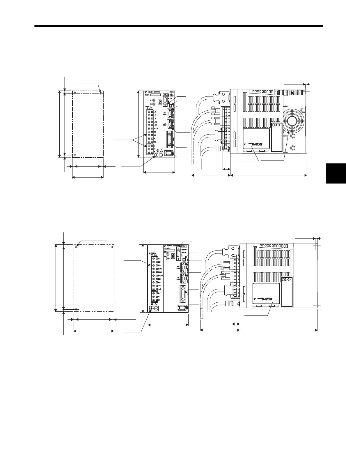
3.6.5 Single-phase 200 V, 750 W, and Three-phase 200 V, 1.0 kW
3.6.6
Three-phase
200 V, 1.5 kW
70 (2.76)
150 (5.91)
CN1
CN2
CN5
CN6A
CN6B
Terminals
Mounting Hole Diagram
CN3
3-M4 screw
70 (2.76)
6
(0.24)
(6)
(0.24)
(Mounting pitch)
(Mounting pitch)
139.5±0.5 (5.49±0.02)
58±0.5
(2.28±0.02)
(5)
(0.20)
5.5
(0.22)
150 (5.91)
180 (7.09)
(75)
(2.95)
18
(0.71)
(5) (0.20)
Nameplate
Cooling fan
Units: mm (in)
Approx. mass: 1.4 kg (3.09 lb)
Ground
terminal
2
×
M4
screws
0
1
2
3
4
5
6
7
8
9
A
B
C
D
E
F
0
1
2
3
4
5
6
7
8
9
A
B
C
D
E
F
180 (7.09)
18
(0.71)
(4) (0.16)
(75)
(2.95)
5
(0.20)
150 (5.91)
5.5
(0.22)
139.5±0.5 (5.49±0.02)
(5) (0.20)
(5) (0.20)
(Mounting pitch)
(Mounting pitch)
90 (3.54)
80±0.5
(3.15±0.02)
3-M4
screws
Mounting Hole Diagram
Nameplate
CN1
CN2
90 (3.54)
150 (5.91)
Two
terminal
types
CN3
CN5
CN6A
CN6B
0
1
2
3
4
5
6
7
8
9
A
B
C
D
E
F
0
1
2
3
4
5
6
7
8
9
A
B
C
D
E
F
Ground
terminal
2
×
M4
screws
Units: mm (in)
Approx. mass: 2.1 kg (4.63 lb)
SIEPS80000025.book 19 ページ 2004年10月25日 月曜日 午前11時57分