5.3 Examples of I/O Signal Connections
5-9
5
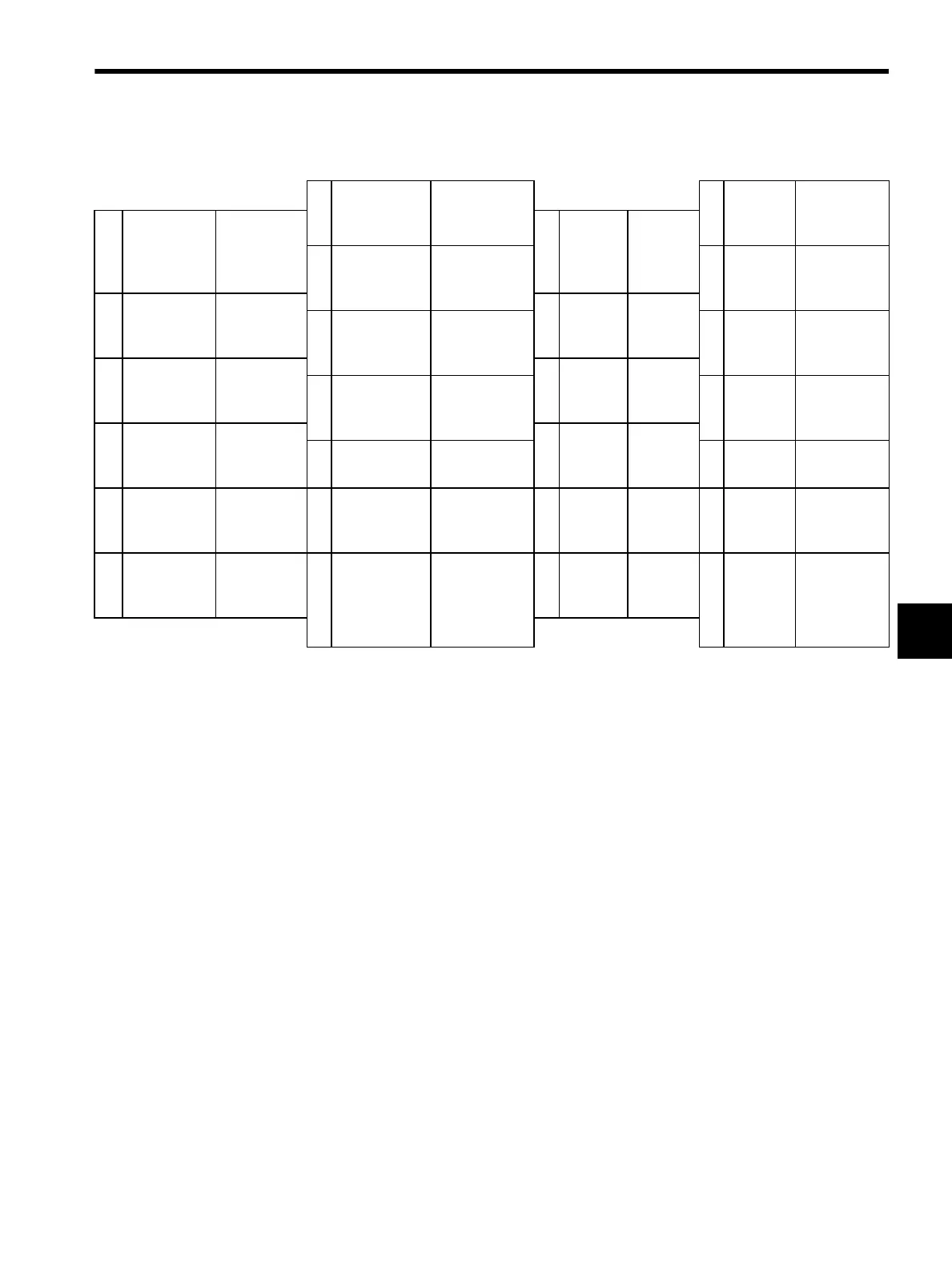
5.3.2 I/O Signal Connector (CN1) Terminal Layout
Note: 1. Do not use unused terminals for relays.
2. Connect the shield of the I/O signal cable to the connector shell.
Connect to the FG (frame ground) at the SERVOPACK-end connector.
1 +24VIN External input
power supply
14 ALM- Servo alarm
signal output
-
2 CCW-OT CCW run
prohibit
signal
15 MS_G Module
status
output
(green)
3 CW-OT CW run
prohibit signal
16 MS_R Module
status output
(red)
4 HOME Home signal
input
17 MS-COM Module
status
common
5 EXSTOP+ External stop
signal input +
18 NS_G Network
status output
(green)
6 EXSTOP- External
stop signal
input -
19 GND Ground
7 USER0 User input
signal 0
20 NS_COM Network
status
common
8 USER1 User input
signal 1
21 ENC_A+ External
encoder
A
9 USER+ User signal
output +
22 ENC_A- External
encoder A
10 USER User signal
output -
23 ENC_B+ External
encoder
B
11 BRK+ Brake signal
output +
24 ENC_B- External
encoder B
12 BRK- Brake signal
output -
25 ENC_C+ External
encoder
C
13 ALM+ Servo alarm
signal output +
26 ENC_C- External
encoder C
SIEPS80000025.book 9 ページ 2004年10月25日 月曜日 午前11時57分