9.1 Troubleshooting
9-9
9
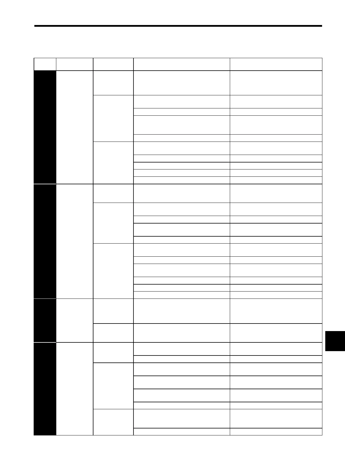
A.410
Undervoltage
(Detected when
the
SERVOPACK
main circuit DC
voltage is
approx. 170 V or
less.)
(Detected when
the power to the
main circuit was
turned ON)
Occurred when the
control power sup-
ply was turned
ON.
A SERVOPACK board fault occurred. Replace the SERVOPACK.
Occurred when the
main circuit power
supply was turned
ON.
The AC power supply voltage is 120 V or less. AC power supply voltage must be within the
specified range.
The fuse of the SERVOPACK is blown out. Replace the SERVOPACK.
Inrush current limit resistor disconnection
(abnormal power supply voltage? inrush current
limit resistor overload?)
Replace the SERVOPACK (check the power
supply voltage, and reduce the number of times
of main circuit ON/OFF operation.)
A SERVOPACK fault occurred. Replace the SERVOPACK.
Occurred during
normal operation.
Lowered AC power supply voltage (large voltage
drop?)
AC power supply voltage must be within the
specified range.
A temporary power failure occurred. Reset the alarm and restart the operation.
The servomotor cable is short-circuited. Repair or replace the servomotor cable.
The servomotor is short-circuited. Replace the servomotor.
A SERVOPACK fault occurred. Replace the SERVOPACK.
A.510
Overspeed
(Detected when
the feedback
speed is the max-
imum motor
speed × 1.1 or
more.)
Occurred when the
control power sup-
ply was turned ON
A SERVOPACK board fault occurred. Replace the SERVOPACK.
Occurred in servo
ON status.
Incorrect order of phases U, V, and W in the ser-
vomotor wiring.
Correct the servomotor wiring.
The encoder wiring is incorrect. Correct the encoder wiring.
Malfunction due to noise interference in the
encoder wiring
Take measures against noise for the encoder
wiring.
A SERVOPACK fault occurred. Replace the SERVOPACK.
Occurred when the
servomotor started
running or at high
speed run.
Incorrect order of phases U, V, and W in the ser-
vomotor wiring.
Correct the servomotor wiring.
The encoder wiring is incorrect. Correct the encoder wiring.
Malfunction occurred due to noise interference in
the encoder wiring
Take measures against noise for the encoder
wiring.
The position/speed reference input is too large. Reduce the reference value.
The setting of reference input gain is incorrect. Correct the reference input gain setting.
A SERVOPACK board fault occurred. Replace the SERVOPACK.
A.710
Overload: High
Load
Occurred when the
control power sup-
ply was turned
ON.
A SERVOPACK board fault occurred. Replace the SERVOPACK.
Occurred when the
servo was turned
ON.
Faulty servomotor wiring (faulty wiring and con-
nection)
Correct the servomotor wiring.
A.720
Overload:
Low Load
Occurred when the
servo was turned
ON.
Faulty encoder wiring (faulty wiring and connec-
tion)
Correct the encoder wiring.
A SERVOPACK fault occurred. Replace the SERVOPACK.
Occurred when the
servomotor did not
run by the refer-
ence input.
Faulty servomotor wiring (faulty wiring and con-
nection)
Correct the servomotor wiring.
Faulty encoder wiring (faulty wiring and connec-
tion)
Correct the encoder wiring.
The starting torque exceeds the maximum torque. Reconsider the load and operation conditions,
or reconsider the servomotor capacity.
A SERVOPACK fault occurred. Replace the SERVOPACK.
Occurred during
normal operation.
The effective torque exceeds the rated torque, or
the starting torque largely exceeds the rated
torque.
Reconsider the load and operation conditions,
or reconsider the servomotor capacity.
A SERVOPACK fault occurred. Replace the SERVOPACK.
Table 9.3 Alarm Display and Troubleshooting (Cont’d)
Alarm
Display
Alarm Name
Situation at Alarm
Occurrence
Cause Corrective Actions
SIEPS80000025.book 9 ページ 2004年10月25日 月曜日 午前11時57分