10
-24
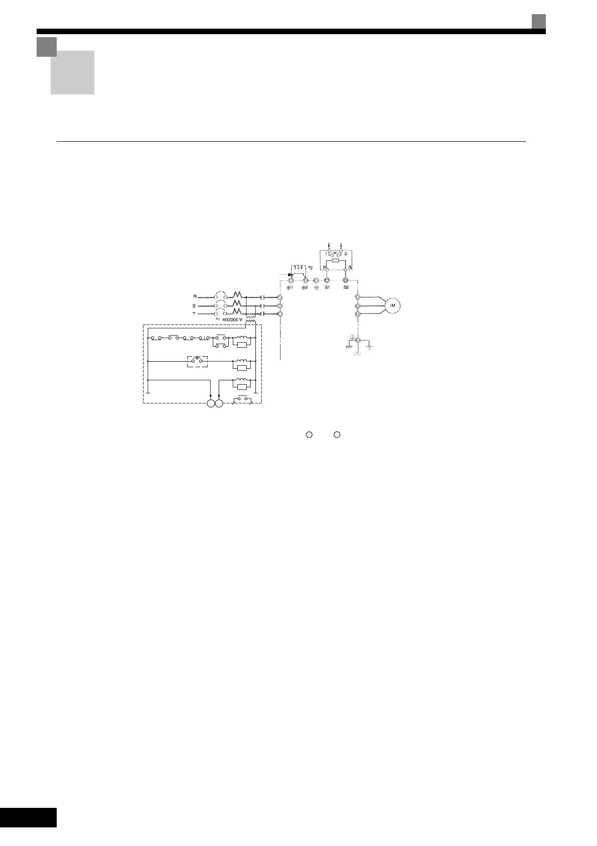
Wiring Examples
This section provides wiring examples to connect a Braking Unit and other peripheral devices to the main
circuits, examples of wiring a transformer to Inverter I/O, and other aspects of Inverter wiring.
Using a Braking Resistor Unit
This example shows wiring for a Braking Resistor Unit.
CIMR-G7A20P4 to -G7A2015 (200 V Class Inverters of 0.4 to 15 kW)
CIMR-G7A40P4 to -G7A4015 (400 V Class Inverters of 0.4 to 15 kW)
* 1. A transformer is not required for 200 V Class Inverter.
* 2. Remove the short-circuit bar (standard equipment) from between 1 and 2 before you connect a DC Reactor (optional).
* 3. Disable the stall prevention during deceleration (set constant L3-04 to 0) when using a Braking Resistor Unit. If this user constant is not
changed to disable stall prevention, the system may not stop in the set deceleration time.
* 4. When connecting a separately-installed type Braking Unit (model CDBR) to Inverters with built-in braking transistor (200 V/400 V 15 kW
or less), connect the B1 terminal of the Inverter to the + terminal of the Braking Unit and connect the - terminal of the Inverter to the - ter-
minal of the Braking Unit. The B2 terminal is not used in this case.
Fig 10.13
THRX
THRX
12
TRX
TRX
MBMC
2MCCB
MA MC
OFF
ON
MC
MC
SA
SA
SA
Braking Resistor Unit
(overheat contacts)
Fault contacts
3-phase power supply,
200 to 240 V at
50/60 Hz or 380 to
480 V at 50/60 Hz
A sequence is required to turn
OFF the power supply for the ther-
mal relay trip contacts of the Brak-
ing Resistor Unit.
Short-circuit bar
DC Reactor to
improve input
power factor
(Optional)
Braking Resistor overheating contacts
(Thermal overload relay trip contacts)
Braking Resistor Unit
*3
Inverter
Motor
(200 V Class Inverters: Ground to
100 Ω max., 400 V Class Inverters:
Ground to 10 Ω max.)
R/L1
S/L2
T/L3
U/T1
V/T2
W/T3
MC
*4
Ground Fault Interrupter or Molded-case Circuit Breaker
TOE-S616-60.1.book 24 ページ 2017年8月4日 金曜日 午後3時41分

 Loading...


