10
-30
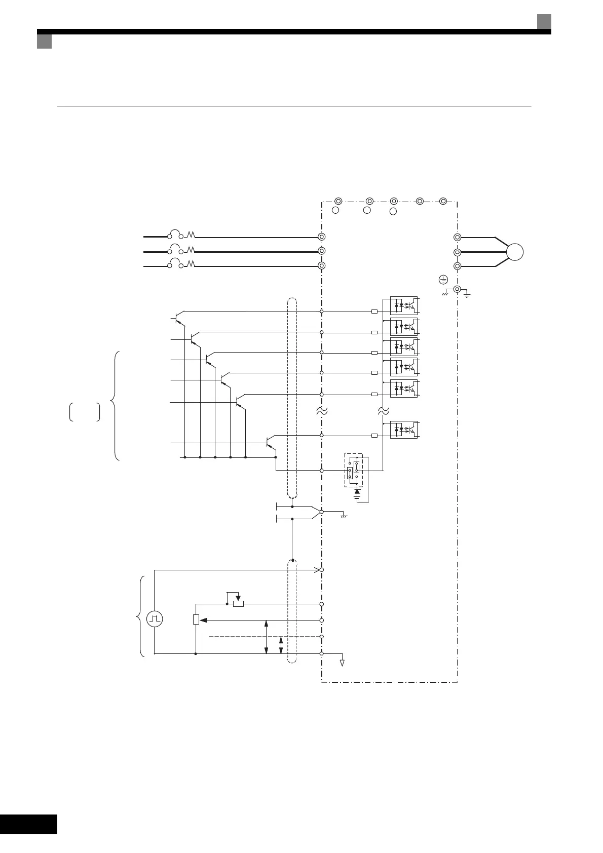
Using Transistors for Input Signals and a +24-V Common in Sourcing
Mode
Set CN5 (shunt connector) on the control board to PNP as shown below for a sequence that uses a PNP tran-
sistor for an input signal (+24-V common and sourcing mode) and an internal +24-V power supply.
Fig 10.19
Inverter
U/T1
V/T2
W/T3
IM
Ground
P
P
4 to 20 mA
0 to +10 V
Pulse train input
RP
+V
A1
A2
AC
0 V
Frequency setting
adjustment
Frequency
setter
2 kΩ
External
frequency
references
2 kΩ
2
1
3
3-phase power
T/L3
S/L2
R/L1
Ground Fault Interrupter or Molded-case Circuit Breaker
T
S
R
E(G)
Shield wire
connection terminal
-
B2B1
+ 1 + 2
+24 V 8 mA
Motor
Multi-step
speed setting 1
Emergency stop
(NO contact)
Forward Run/Stop
Reverse Run/Stop
External fault
Fault reset
S5
S12
SC
S1
S2
S3
S4
Multi-function
contact inputs
Factory
settings
CN5 (PNP setting)
+24 V
Master speed pulse train
0 to 32 kHz (3 kΩ)
0 to 10 V (20 kΩ)
4 to 20 mA (250Ω)
0 to 10 V (20 kΩ) input
High level: 3.5 to 13.2 V input
Frequency setting power
+15 V 20 mA
Master speed reference
Master speed reference
TOE-S616-60.1.book 30 ページ 2017年8月4日 金曜日 午後3時41分

 Loading...


