10
-42
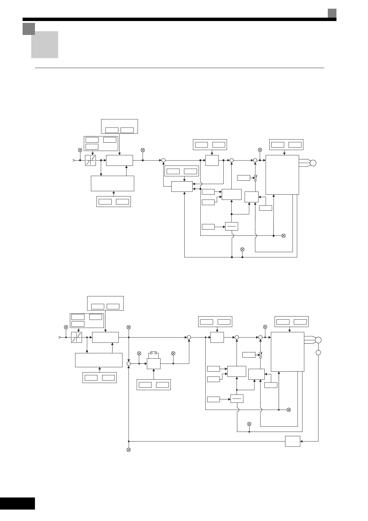
Control Block Diagrams
Control Block Diagrams for Control Methods
The control block diagrams of the control methods are provided in Fig 10.22 to Fig 10.26.
Control Block Diagram for V/f
Fig 10.22 Control Block Diagram for V/f (A1-02 = 0)
Control Block Diagram for V/f with PG
Fig 10.23 Control Block Diagram for V/f with PG (A1-02 = 1)
Speed reference
fref
U1-01
Soft starter
to
L3-01 L3-06
Acceleration and
deceleration times
C1-01 C1-02
U1-20
f0
+
+
Slip
compensation
+
+
C4-01
C4-02
Torque
compensation
1
1+ST
U1-06
Hunting
prevention
N1-01
+
+
IM
Inverter
N1-02
U1-02
fout
iqfb
idfb
to
C3-01 C3-04
d2-01 d2-03
E1-09
to
E1-04 E1-13
E2-05
U1-18
to
C6-02 C6-05
to
SFS output
Output
frequency
Output voltage
Motor secondary
current
Frequency
reference
f1
fs
*
Stall prevention processing
(acceleration and deceleration
rate correction)
V/f
pattern
Speed
reference
fref
U1-01
Stall prevention processing
(acceleration and deceleration
rate correction)
Soft starter
to
L3-01 L3-06
Acceleration and
deceleration times
C1-01 C1-02
U1-20
f0
+
−
fnfb
U1-21
ASR
IRST
(Integral
short-circuit)
U1-22
+
+
+
+
C4-01
C4-02
1
1+ST
U1-06
Hunting
prevention
N1-01
+
+
IM
Inverter
N1-02
U1-02
fout
iqfb
idfb
PG
Speed
detector
to
C5-01 C5-04
d2-01 d2-03
E1-09
to
E1-04 E1-13
E2-05
U1-18
to
C6-02 C6-05
to
SFS output
ASR input
ASR output
Output
frequency
Output voltage
Motor secondary
current
Frequency
reference
U1-05
Motor speed
f1
V/f
pattern
Torque
compensation
TOE-S616-60.1.book 42 ページ 2017年8月4日 金曜日 午後3時41分

 Loading...


