6
-122
Setting the V/f Pattern
In V/f control method, you can set the Inverter input voltage and the V/f pattern as the need arises.
Related Constants
Con-
stant
Number
Name
Description
Setting
Range
Factory
Setting
Change
during
Opera-
tion
Control Methods
MEMO
BUS
Regis-
ter
Display
V/f
V/f
with
PG
Open
Loop
Vector
1
Flux
Vec-
tor
Open
Loop
Vector
2
E1-01
Input voltage
setting
Set the Inverter input voltage in 1
volt.
This setting is used as a reference
value in protection functions.
155 to
255
*1
200 V
*1
NoQQQQQ300H
Input Voltage
E1-03
V/f pattern
selection
0 to E: Select from the 15 preset
patterns.
F: Custom user-set patterns
(Applicable for settings E1-04
to E1-10.)
0 to F F No Q Q No No No 302H
V/F Selection
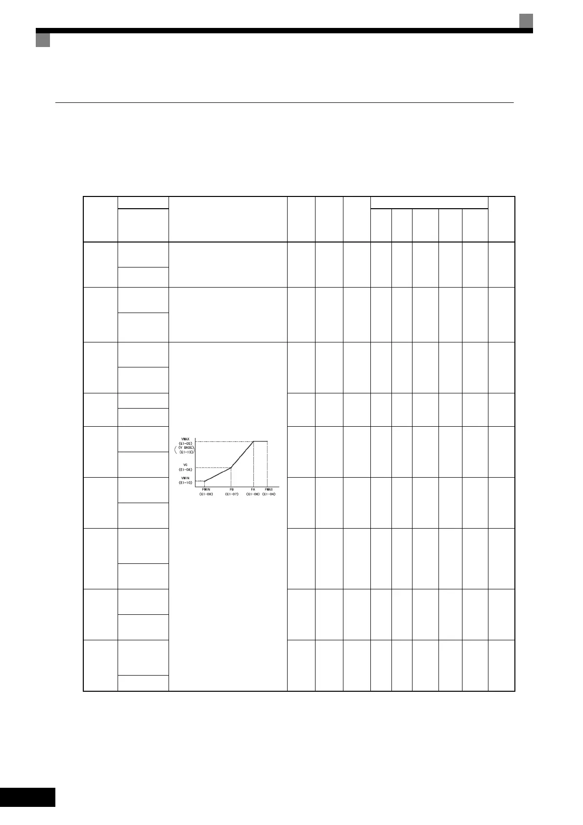
E1-04
Max. output
frequency
To set V/f characteristics in a
straight line, set the same values for
E1-07 and E1-09. In this case, the
setting for E1-08 will be disre-
garded.
Always ensure that the four fre-
quencies are set in the following
manner:
E1-04 (FMAX) ≥ E1-06 (FA) > E1-
07 (FB) ≥ E1-09 (FMIN)
40.0 to
400.0
*5
60.0
Hz
*2
NoQQQQQ303H
Max
Frequency
E1-05
Max. voltage 0.0 to
255.0
*1
200.0
V
*1*2
NoQQQQQ304H
Max Voltage
E1-06
Base
frequency
0.0 to
400.0
*5
60.0
Hz
*2
NoQQQQQ305H
Base
Frequency
E1-07
Mid. output
frequency
0.0 to
400.0
3.0 Hz
*2
No A A A No No 306H
Mid
Frequency A
E1-08
Mid. output
frequency
voltage
0.0 to
255.0
*1
11.0 V
*1 *2
No A A A No No 307H
Mid Voltage
A
E1-09
Min. output
frequency
0.0 to
400.0
*5
0.5 Hz
*2
NoQQQAQ308H
Min
Frequency
E1-10
Min. output
frequency
voltage
0.0 to
255.0
*1
2.0 V
*1 *2
No A A A No No 309H
Min Voltage
TOE-S616-60.1.book 122 ページ 2017年8月4日 金曜日 午後3時41分

 Loading...


