Individual Functions
6-
123
* 1. These are values for a 200 V Class Inverter. Values for a 400 V Class Inverter are double.
* 2. The factory setting will change when A1-02 (Control Method) is changed. (The factory settings of the open-loop vector 1 control are given.)
* 3. E1-11 and E1-12 are disregarded when set to 0.0.
* 4. When E1-13 (Base Voltage) is set to 0.0, control is performed with E1-13 equal to E1-05 (Max. Voltage).
E1-05 and E1-13 are automatically set to the same values when autotuning is performed.
* 5. The setting range for open-loop vector 2 control is 0 to 66.0 (0 to 132.0 for PRG 103).
For the 400 V Class, there are limitations on the maximum output frequency depending on the setting for the carrier frequency and capacity.
The maximum output frequency for 400 V, 90 to 110 kW is 250 Hz. The maximum output frequency for 400 V, 132 to 300 kW is 166 Hz.
Setting Inverter Input Voltage
Set the Inverter input voltage correctly in E1-01 to match the power supply voltage. This set value will be the
standard value for the protection function and similar functions.
The overvoltage detection level (OV) and the braking transistor operation level (BTR) vary depending on the
input voltage as shown in the following table.
* These are values of operation levels for braking transistors built in Inverters of 0.4 to 15 kW. Refer to YASKAWA AC Drive Option Braking Unit, Braking
Resistor Unit Installation Manual (TOBPC72060000/TOBPC72060001) for operation levels for separately-installed type Braking Resistor Units.
If selecting a fixed V/f pattern (E1-03 = 0 to E) in V/f control the values of the max. voltage (E1-05), the mid.
Output frequency voltage (E1-08), and the min. output frequency voltage (E1-10) will change if the value for
the input voltage setting (E1-01) is changed.
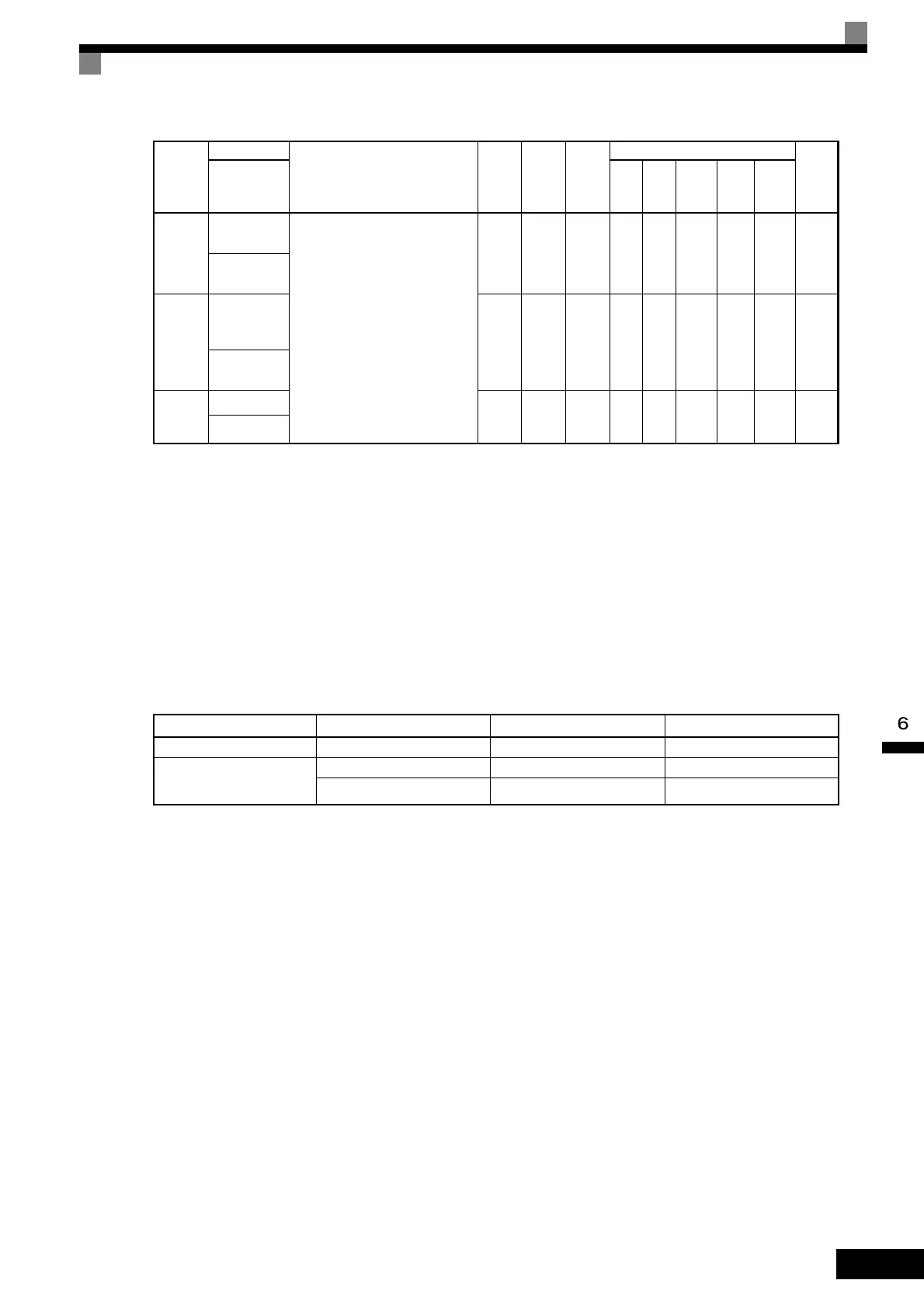
E1-11
Mid. output
frequency 2
Set only to fine-adjust V/f for the
output range. Normally, this setting
is not required.
0.0 to
400.0
*5
0.0 Hz
*3
NoAAAAA30AH
Mid
Frequency B
E1-12
Mid. output
frequency
voltage 2
0.0 to
255.0
*1
0.0 V
*3
NoAAAAA30BH
Mid Voltage
B
E1-13
Base voltage 0.0 to
255.0
*1
0.0 V
*4
NoAAQQQ30CH
Base Voltage
Inverter Class E1-01 Setting OV Detection Level
BTR Operation Level
∗
200 V Class All values Approx. 410 V Approx. 394 V
400 V Class
400 V or more Approx. 820 V Approx. 788 V
Less than 400 V Approx. 720 V Approx. 682 V
Con-
stant
Number
Name
Description
Setting
Range
Factory
Setting
Change
during
Opera-
tion
Control Methods
MEMO
BUS
Regis-
ter
Display
V/f
V/f
with
PG
Open
Loop
Vector
1
Flux
Vec-
tor
Open
Loop
Vector
2
TOE-S616-60.1.book 123 ページ 2017年8月4日 金曜日 午後3時41分

 Loading...


