6
-166
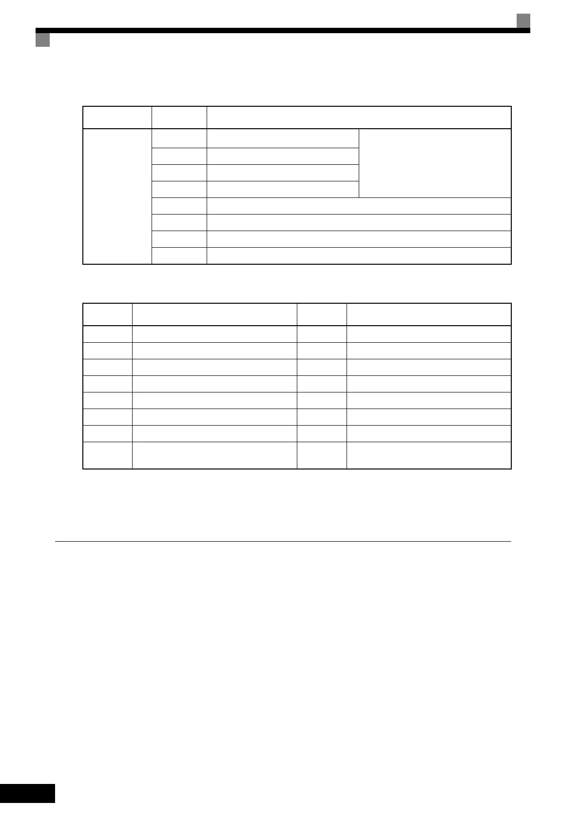
F5-09 Set to 1
The following table shows the code outputs.
F5-09 Set to 2
Output depends on the settings in F5-01 to F5-08.
Using an Analog Reference Board
AI-14B provides 3 channels of bi-polar inputs with 14-bit A/D conversion accuracy (and a sign bit). The func-
tion of each channel is determined by the setting of F2-01.
AI-14U provides 2 channels of bi-polar inputs with 14-bit A/D conversion accuracy. Channel 1 is a voltage
input and channel 2 is a current input. The sum of channels 1 and 2 is a frequency input. F2-01 does not need
to be set for the AI-14U.
Set Value
Terminal
Number
Output Details
1: Binary code
output
TD5-TD11 bit 0
Encoded output
(Refer to table below)
TD6-TD11 bit 1
TD7-TD11 bit 2
TD8-TD11 bit 3
TD9-TD11 Zero-speed detected
TD10-TD11 Speed agreement
TD1-TD2 Operating
TD3-TD4 Minor fault
Bits 3, 2, 1,
and 0
Output Details
Bits 3, 2, 1,
and 0
Output Details
0000 No error 1000 External fault (EFXX)
0001 Overcurrent (SC, OC, GF) 1001 Controller error (CPFXX)
0010 Overvoltage (OV) 1010 Motor overload (OL1)
0011 Inverter overload (OL2) 1011 Not used
0100 Inverter overheated (OH, OH1) 1100 Power loss (UV1, UV2, or UV3)
0101 Overspeed (OS) 1101 Speed deviation (DEV)
0110 Fuse blown (PUF) 1110 PG open circuit (PGO)
0111
Dynamic braking resistor (RH)
Injection brake transistor error (RR)
1111 Not used
TOE-S616-60.1.book 166 ページ 2017年8月4日 金曜日 午後3時41分

 Loading...


