Adjusting frequency setting signal I
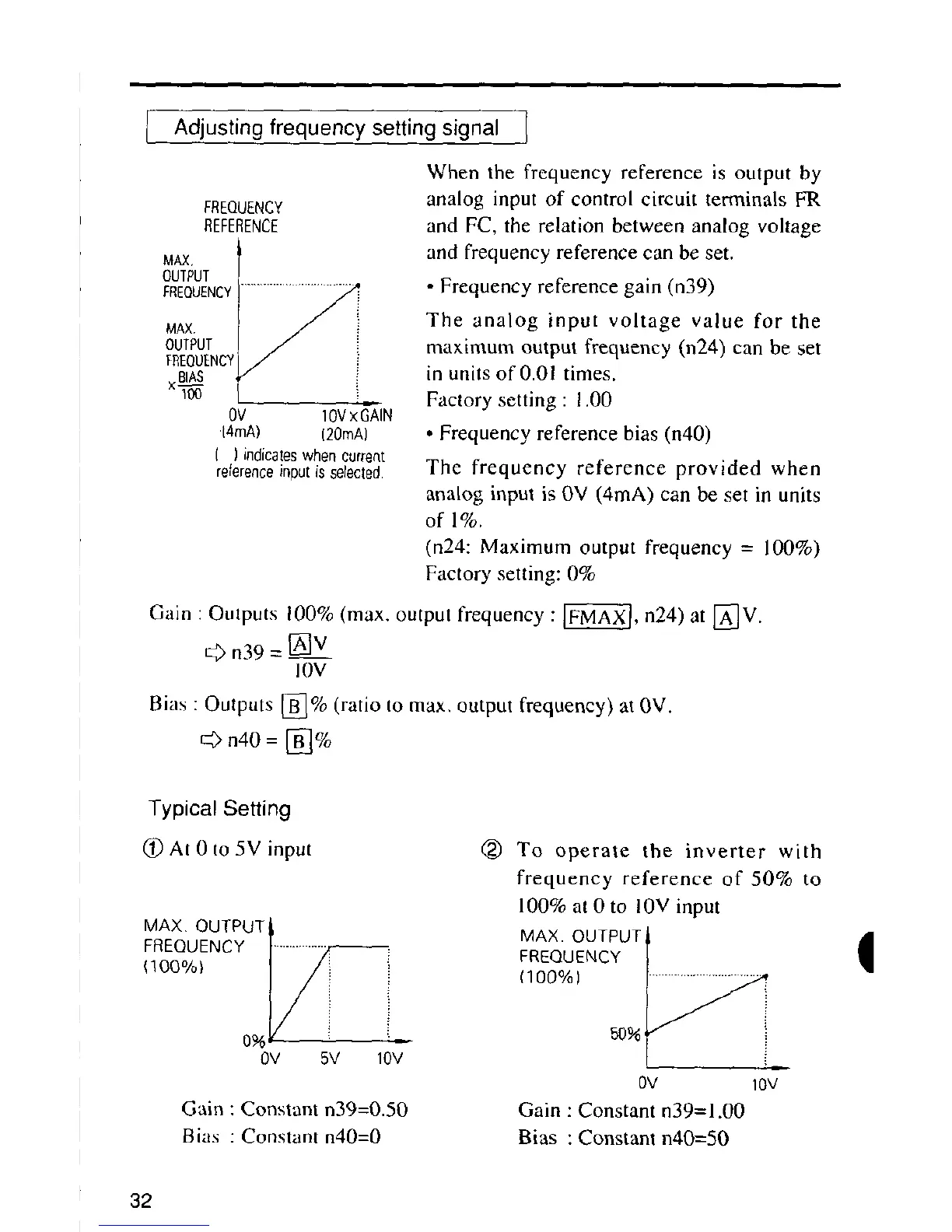
When the frequency reference is output by
FREQUENCY analog input of control circuit terminals FR
REFERENCE and FC, the relation between analog voltage
and frequency reference can beset.
MAX,
OUTPUT
l
FREQUENCY................................_ • Frequency reference gain (n39)
MAX The analog input voltage value for the
OUTPUT maximum output frequency (n24) can be set
FREOUENCYI
BIAS ,F" inunits of 0.01 times.
xT_ _ Factory setting : 1,00
0V IOVxGAIN
14mA) (20mA) • Frequency reference bias (n40)
( )indicateswhencuo-ent
reference input isse/ecled. The frequency reference provided when
analog input is OV (4mA) can be set in units
of 1%.
(n24: Maximum output frequency = 100%)
Factory setting: 0%
Gain : Outputs 100% (max. output frequency : [_A-X], n24) at [_V.
t:_ n39 = [_V
I0V
Bias : Outputs [_% (ratio to max, output frequency) at 0V.
_vn40=[_%
Typical Setting
(_At0to5Vinput (_) To operate the inverter with
frequency reference of 50% to
100% at 0 to 10V input
MAX.OUTPUT_ MAX.OUTPUT_
(100%) 1 _i FREQUENCY
0V 5V 10V
0V 10V
Gain :Constan't n39=0.50 Gain : Constant n39=1.00
Bias : Constant n40=0 Bias :Constant n40=50
32

 Loading...


