9. SPECIFICATIONS
• Standard Specifications
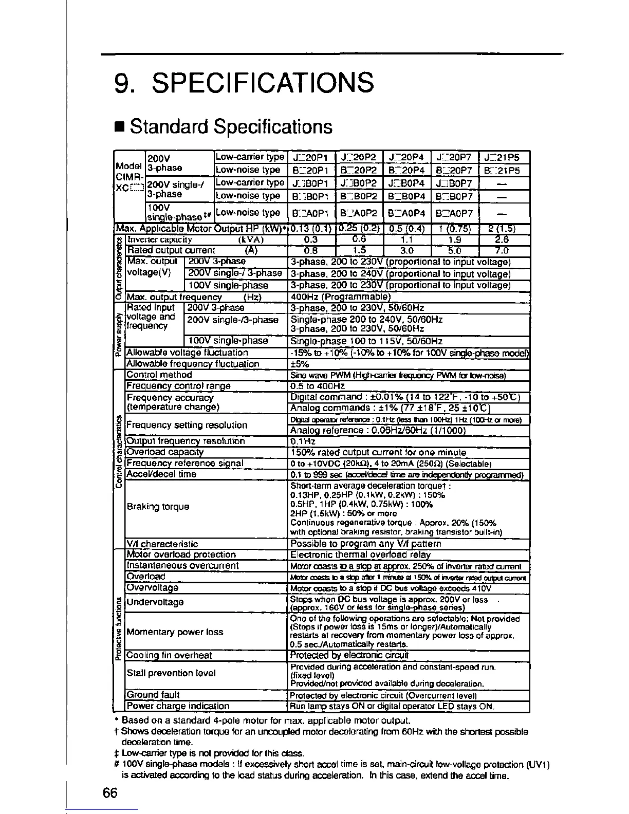
200V Low-carrier type JL_20P1 J__20P2 J_20P4 J_-2OP7 J_21P5
ledel 3-phase Low*noisetype B_E20Pt B-20P2 B-_20P4 8_20P7 B;21P5
IMR-
C'_] 20OV single-/ Low-carrier type J}]BOP1 J_]BOP2 J_BOP4 JZBOP7 --
3-phase Low-noise type B_]BOP1 B-_BOP2 B_BOP4 B_BOP7 --
100V
sin._e__haset# Low-noise type B-AOPt BL_AOP2 BZAOP4 B__AOP7 --
lax. ApplicableMotorOutputHP(kW)*O.13(O.1) 0.25(0,2) 0.5{0.4 / 1(0.751 2(1.5)
tnvcrtcr capacity (kVA) 0.3 0.6 1.1 1.9 2.6
Rated output current (A) 0.8 1.5 3.0 5.0 7.0
Max. output I 200V 3-phase 3-phase, 200 to 230V (proportional to input voltage)
voltage(V) 1200V single+/3-phase 3-phase, 200 to 240V (proportional to input voltage 1
I
t OOV single-phase 3-phase, 200 to 230V (proportional to input voltage)
Max. output frequency (Hz) 4O0Hz (Programmable)
Rated input 1200V 3_ho.se 3-phase, 200 to 230V, 5016OHz
voltage
and
2O0V
single-/3-phase
3-p_ase, 200 to 230V, 5O/6OHz
frequency 100V single-phase Sin le-phase 200 to 240V, 50/60HzSingle-phase 100 to 115V, 50/6OHz
Allowable volta_le fluctuation -15% to +100 (-10% to +10% for 100V si_e-pha._ mode
Allowable frequency ffuctualion :1:5%
Control method S_newave PWM (Hi_t:K_anierfrequenc). PWM forIow-notseI
Frequency control range 0.5 to 400Hz
Frequency accuracy Digital command : ¢0.01% (14 to 122"F. -t0 to +50"C)
(temperature change) Analog commands : ±1% (77 ±18"F. 25 ±t0"C)
Distaloperat_reference: 0.1Hzfktsslien 100Hz)1Hz (100P__ mote)
Frequency setting resolution Analog reference : 0.O6Hz/60Hz (1/100O)
Output lrequenc 7 resotution 0.1 Hz
Ovedoad capacity 150% rated output current for one minute
Frequency reference signal 0 to +t0VDC (20k_. 4 to 20mA (250_) (Saiectable_
Accob'decel time 0.1 to 999 sec (_ _ne am _ programmed)
Short-term average deceleration torquer :
O.13HP, 0,25HP (0.1kW, 0.2kW) : 150%
Braking torque O.5HP. 1HP (0.4kW, 0.75kW) : 100%
2HP (t.5kW) : _ or more
Continuous regenerative torque : Approx. 2(P/o (150%
with optional braking resistor, braking transistor built*in)
V/f charactedstic Possible to program an)' V/f pattern
Motor overload protection Electronic thermal ovedoad relay
Instantaneous overcurrent Motor coaststo a stopm appmx. 25o% ofinverterrated oJ_en!
Overload Minorc=:_s==oa s=paf_ 1 ntnutem 150%o_b_'_a rmedompuJ_
Ovewoltage Moto_ o_sts to a stopif DE;bus votta_ excseds 410V
Stops when OC bus voltage isapprox. 200V or tess •
Unden/oltage
(approx. 16OV or less for sin,qle-phase sedes)
One of the tol_owing operations are seteotabls: Not provided
Stops if power loss is 15ms or leng er)/Automatically
Momentary power loss restarts at recovery rom momentary power loss of approx.
O.5secJAutomagcalty restarts.
Coolin_l fin overheat Protected by electronic circuit
provided during acceleration and constant-speed run.
Stall prevention level (fixed level)
Provided/not provided avai]abls dudng deceleration.
Ground fault Protected by electronic c_rcuit(Overcurrent level1
Power charge indication Run lamp stays ON or digital operator LED stays ON.
• Based on a standard 4-pole motor for max. applicable motor output.
t SHOWSdeceler_ion torque for an uncoupled motor decelerating from 60Hz with the shortest possible
deceleration time.
;l:Low-carrler type is not provided for this class.
# t00V singkPphase models : If excesswely short accel time is set, main-clrcuit fow-vollege Wotection (UVt)
is activated according to the load status duhng acceleration. In this case, extend the accel time.
66

 Loading...


