• Recommended Peripheral Devices
it is recommended that the following peripheral devices should be mounted
between the AC main circuit power supply and VS mini input terminals
LI(R), N/L2(S) and L3(T)+
• MCCB (Molded-case circuit breaker) :
Be sure to connect it for wiring protection, m
• Magnetic contactor:
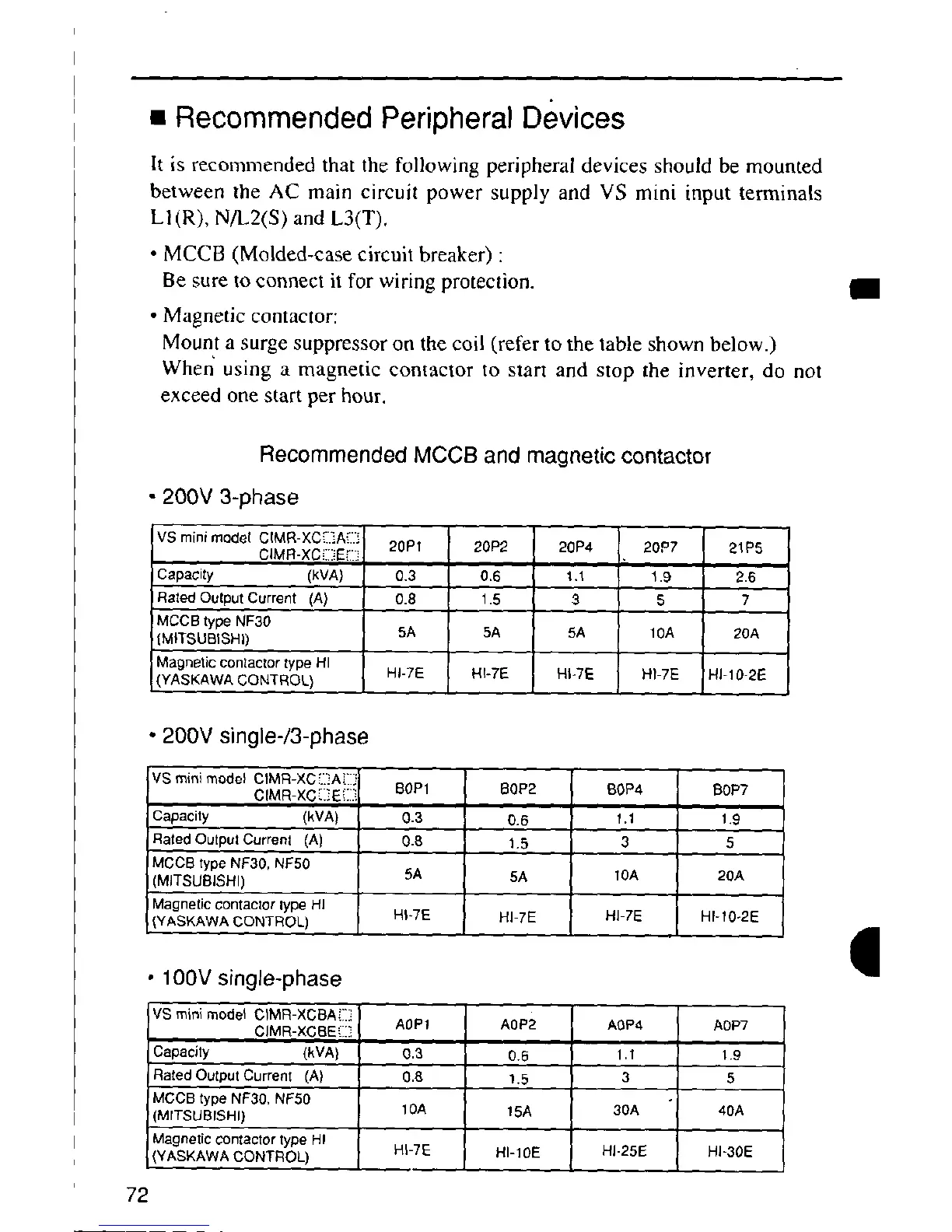
Mount a surge suppressor OR the coil (refer to the table shown below.)
When using a magnetic contactor to start and stop the inverter, do not
exceed one start per hour.
Recommended MCCB and magnetic contactor
• 200V 3-phase
vs mini rnedet CtMR-XC[.IA_./3
CIMR-XCI:I[iE[TTI 20P1 20P2 20P4 20P7 2"_P5
Capacity (kVA) 0.3 0,6 1.1 1.9 2.6
RatedOutputCurrent (A) 0.8 1.5 3 5 7
MCCB type NF30
IMITSUBISHI) 5A 5A 5A 10A 20A
Magneticcontactor type HI
(YASKAWA CONTROL) HI-7E HI+7E HI+TE HI-7E RI-10-2E
• 200V single-/3-phase
vs mini model CtMR-XC!.I]AiT
CIMR-XC[_E [_] BOP1 BOP2 BOP4 BOP7
Capacity (kVA) 0.3 0.6 t.1 1.9
Raled Outpul Current (A) 0.8 1.5 3 5
JMCCB type NF30, NF50
J(MITSUBISHI) 5A 5A t0A 2OA
)Magnetic contaclor lype HI
,_YASKAWACONTROL) R$+7E HI 7E HI-7E HI-T0+2E
,iN
• 100V single-phase •
vs mini model CIMR-XCBA[_I.;
CIMR-XCBE(_ AOPt AOP2 AOP¢ AOP7
Capacity (kVA) 0.3 0.6 1.1 1.9
RatedOutputCurrent (A) 0.8 1.5 3 5
MCCB type NF30, NFS0
(MITSUBrSHI) 10A t 5A 30A 40A
Magnetic contactor type HI
i (YASKAWA CONTROL) H$-7E HI-10E HI-25E HI-30E
72

 Loading...


