4-8
IM CA71-E
■ Output Method Based on Three-wire Connection
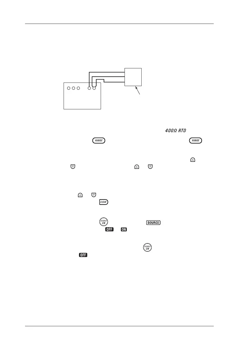
Attach another lead cable to the L output terminal, as shown in the
following gure. The output is provided through the three wires,
H, L and L’. Connect these three wires to the device being calibrated.
CA71
SOURCE Three-wire measuring equipment
H
H
L
L'
L
Three-wire Connection for Resistance Signal Source
Step 1: Using the function selector switch, select
.
Step 2: Using the
key, select the range. Pressing the key
cycles through the 400 Ω, PT100 and JPT100 options.
Step 3: Set the output value digit by digit using each pair of
and
keys. Each press of the or key increases or
decreases the digit. Increasing the digit from 9 or decreasing
it from 0 causes the digit to overow or underow, allowing
you to set the output value without interruption. Holding down
the
or key continuously changes the digit in question.
Pressing the
key initializes the output setpoint to the
default value (0).
Step 4: Pressing the
key causes the indicator on the LCD
to change from to . The calibrator sources the preset
resistance value between the output terminals.
Step 5: To turn off the output, press the
key once again.
The appears on the LCD and the output terminals are
open-circuited.
4.3
Sourcing Resistance or RTD Signal
 Loading...