IM CA71-E
10-3
Method of Calibrator Adjustment
10
10.2 Adjusting Source Functions
10.2 Adjusting Source Functions
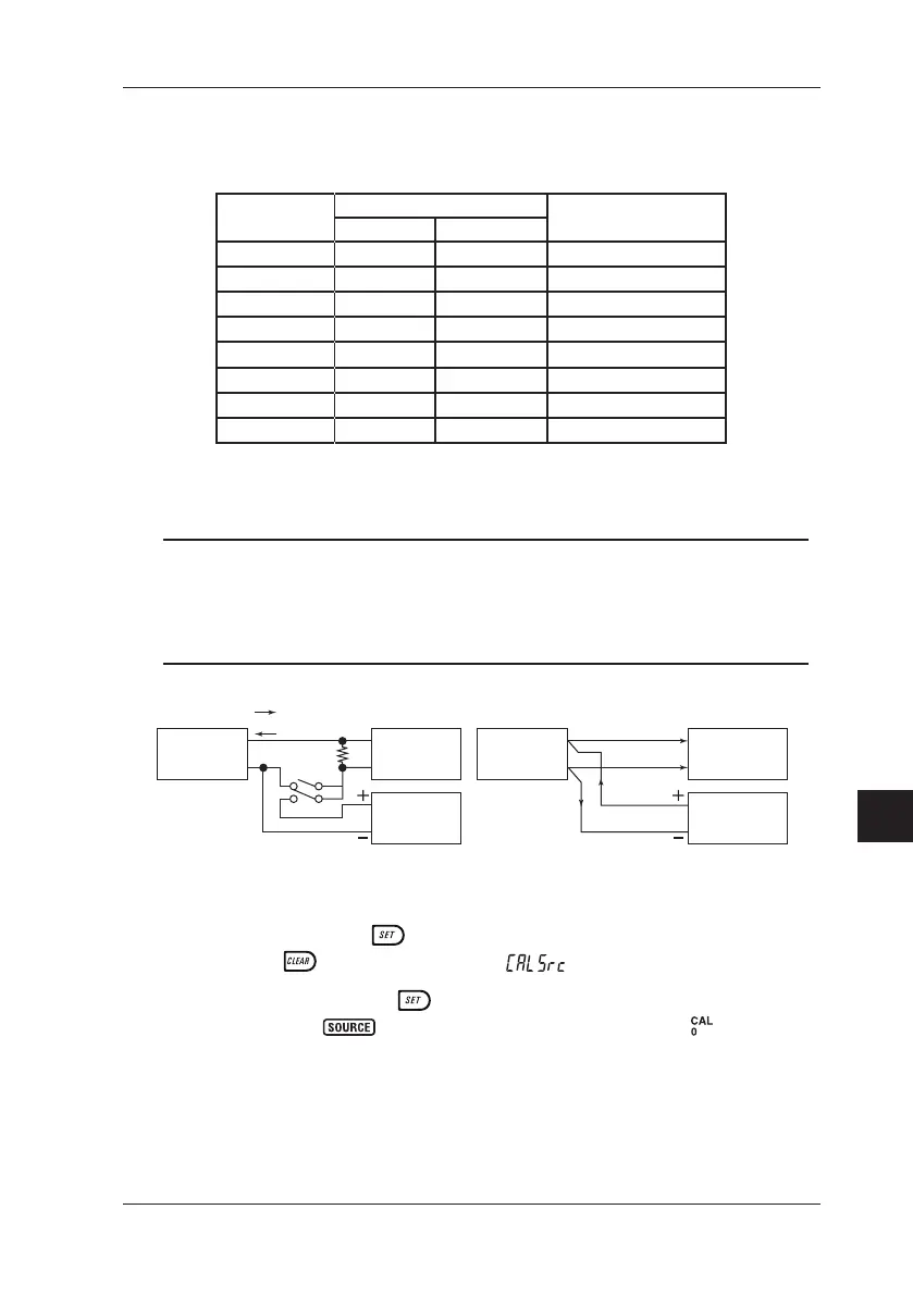
Table 10.1 Adjustment Points of Source Functions
Range
Adjustment Points *
1
Remarks
CAL 0 CAL FS
100 mV 0 100 mV ---
1 V 0 1 V ---
10 V 0 10 V ---
30 V 0 30 V ---
20 mA 0 20 mA See the gure below.
20 mA SINK 0.1 mA 20 mA See the gure below.
400 Ω/1 mA 0 400 Ω Four-wire connection
400 Ω/5 mA 0 400 Ω See the gure below.
*1: Adjust the source functions so that the readings of the calibration standard
(output values of the CA51/71) match the adjustment points listed above.
TIP
• You can also select only the range in need of readjustment to adjust
it separately.
• Always make zero-point (0) adjustments together with full-scale (FS)
adjustments.
CA71
24V
20 mA
20 mA output
SINK
SINK
H
L
Power
supply
H
L
DMM
Voltage range
CA71
5 mA
H
L
High-precision
current source
Standard resistor
100 Ω
20 mA and SINK ranges 400 Ω/5 mA
DMM
Voltage range
Hook-ups for Adjustment
Step 1: Press the
key while simultaneously holding down the
key. The LCD shows .
Step 2: Pressing the
key enters the source CAL mode.
The
indicator blinks on the LCD and the symbol
appears. The calibrator is now ready for the zero-point
adjustment of source functions.
 Loading...