IM CA71-E
12-1
Specications
12
12. Specications
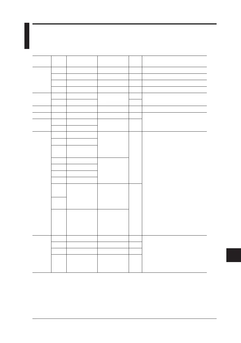
Parameter
DC
voltage
DC
current
mA SINK
Resistance
RTD
TC *
4
Frequency,
pulse
Reference
100 mV
1 V
10 V
30 V
20 mA
4-20 mA
20 mA
400 Ω
Pt100 *
2
JPt100
K
E
J
T
N
L
U
R
S
B
500 Hz
1000 Hz
10 kHz
Pulse
cycle *
5
Range
-10.00 –110.00 mV
0 – 1.1000 V
0 – 11.000 V
0 – 30.00 V
0 – 24.000 mA
4/8/12/16/20 mA
0.1 – 24.000 mA
0 – 400.00 Ω
-200.0 – 850.0°C
-200.0 – 500.0°C
-200.0 – 1372.0°C
-200.0 – 1000.0°C
-200.0 – 1200.0°C
-200.0 – 400.0°C
-200.0 – 1300.0°C
-200.0 – 900.0°C
-200.0 – 400.0°C
0 – 1768°C
600 – 1800°C
1.0 – 500.0 Hz
90 – 1100 Hz
0.9 kHz – 11.0 kHz
1 – 99,999 cycles
Resolution
10 μV
0.1 mV
1 mV
10 mV
1 μA
4 mA
1 μA
0.01 Ω
0.1°C
0.1°C
1°C
0.1 Hz
1 Hz
0.1 kHz
1 cycle
Accuracy
(23±5°C per year)
±(0.02% + 15 μV)
±(0.02% + 0.1 mV)
±(0.02% + 1 mV)
±(0.02% + 10 mV)
±(0.025% + 3 μA)
±(0.05% + 3 μA)
±(0.025% + 0.1 Ω)
±(0.025% + 0.3°C)
±(0.02% + 0.5°C)
(-100°C or greater)
±(0.02% + 1°C)
(less than -100°C)
±(0.02% + 0.5°C)
(0°C or greater)
±(0.02% + 1°C)
(less than 0°C)
±(0.02% + 2.5°C)
(less than 100°C)
±(0.02% + 1.5°C)
(100°C or greater)
±(0.02% + 2°C)
(less than 1000°C)
±(0.02% + 1.5°C)
(1000°C or greater)
±0.2 Hz
±1 Hz
±0.1 kHz
---
Remarks
---
Maximum output: 5 mA
Maximum output: 10 mA
Maximum output: 10 mA
*
1
Maximum load: 12 V
External power supply: 5 to 28 V
Excitation current: 0.5 to 5 mA *
3
If 0.1 mA, add 0.25 Ω or 0.6°C. Subject
device input capacitance: 0.1 µF or less
TC source accuracy does not
include RJ sensor accuracy.
< RJ sensor specs >
Measurement range: -10 to 50°C
Accuracy
(when combined with main unit)
18 to 28°C: ±0.5°C
Other than the above: ±1°C
Output voltage: +0.1 to +15 V
(zero base waveform)
Amplitude accuracy: ±(5% + 0.1 V)
Maximum load current: 10 mA
Contact output
(with 0.0 V amplitude setting, FET switch
ON/OFF)
Maximum open/close voltage/current:
+28 V/50 mA
Temperature coefficient: Accuracy shown above × (1/5)/°C
*1: Output up to 24 V/22 mA is possible when using the AC adapter.
*2: As per JIS C 1604 (ITS-90). IPTS-68 may be selected through internal settings (DIP switch).
*3: Excitation current: If less than 0.1 mA to 0.5 mA, then add [0.025/ls (mA)] Ω or [0.06/ls (mA)]°C.
*4: As per JIS C 1602 (ITS-90) (L and U are DIN specs).
K, E, J, T, N, R, S, and B may be switched to IPTS-68 through internal settings (DIP switch)
(L and U are not switched).
*5: Frequency (interval between one pulse and another) and amplitude during pulse cycle source
may have the same range as during frequency source.
±(% of setting + μV, mV, mA, Ω or °C)
(1) Signal sourcing unit range and accuracy (for both CA51 and CA71)

 Loading...