1-3
IM DLM5058-03EN
1
Component Names and Functions
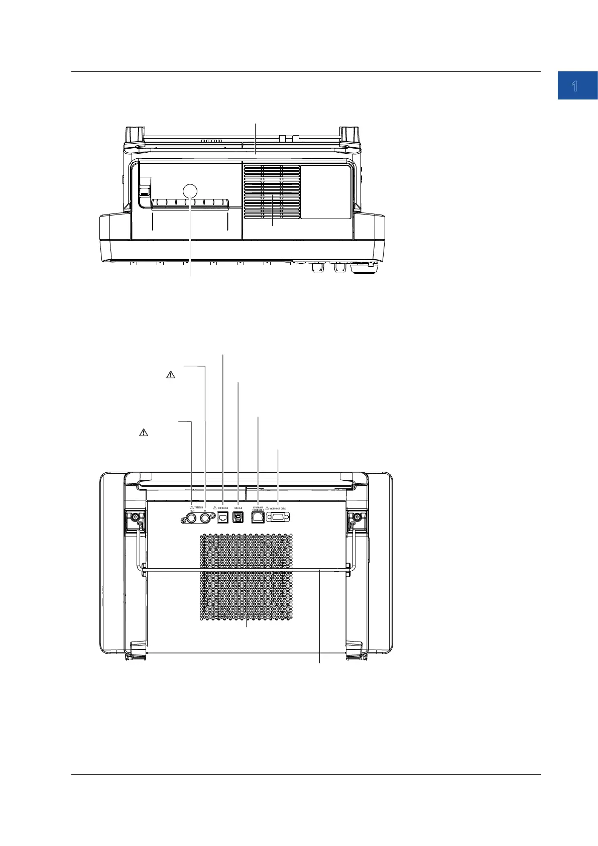
Top Panel
Built-in printer (option)
Inlet holes
Rear Panel
Outlet holes
Stand → sec. 2.2
GO/NO-GO output port
This connector transmits GO/NO-GO result signals. → sec. 4.4
Video Signal Output Connector
Use this connector to view the instrument’s display on an external
display. → sec. 4.3
External trigger
input terminal
USB port for PCs
Use to connect to a PC that has a USB port.
→ Communication Interface User’s Manual
Ethernet port
Used to connect the instrument to a network
→ User’s Manual and Communication Interface User’s Manual
Trigger output
terminal
Use to transmit trigger
signals. → sec. 4.2
Use to apply external
trigger signals.
→ sec. 4.1
1.1 Front, Right, Left, Top, and Rear Panels

 Loading...


