IM 253401-01E
10-20
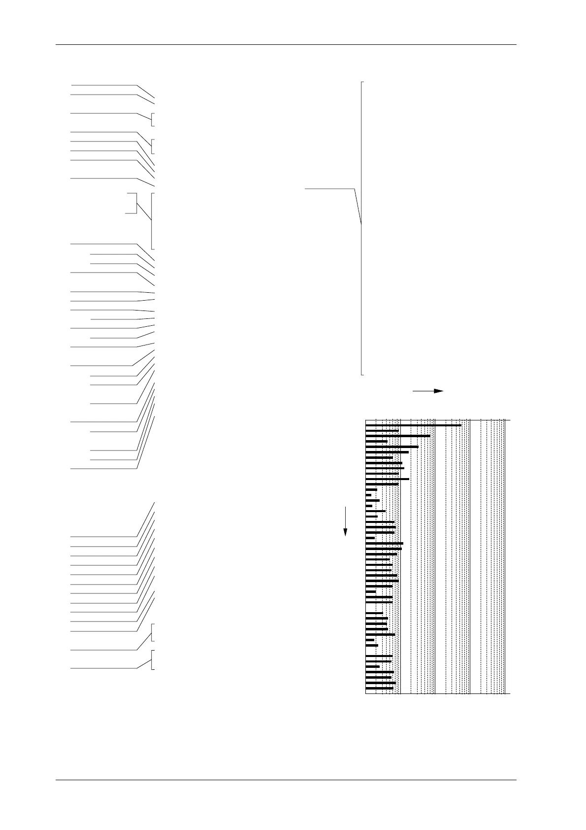
Output example of harmonic analysis data
Refer to the
previous page for
a description
Model : M/253503/HRM
V Range : 15 V
A Range : 0.5A
Function : V 1
Sync : PLL V1
Freq V1 = 60.00 Hz
V1 rms = 5.76 V
A1 rms = 1.4 mA
W1 = -0.001 W
DEG1 = LEAD 153.8 deg
PF1 = -0.897
V1 THD (IEC) = 15.71%
A1 THD (IEC) = - - - oF - - -
Avg (EXP 8 ) = OFF
Scaling = OFF
####### Harmonic Voltage List #######
Or Volt [V] Cont [%] Or Volt [V] Cont [%]
1 5.69 2 0.09 1.60
3 0.68 12.02 4 0.04 0.74
5 0.32 5.63 6 0.16 2.77
7 0.06 1.05 8 0.11 2.01
9 0.12 2.15 10 0.09 1.65
11 0.17 2.96 12 0.08 1.47
13 0.02 0.39 14 0.01 0.25
15 0.02 0.43 16 0.01 0.25
17 0.04 0.63 18 0.02 0.41
19 0.07 1.15 20 0.07 1.31
21 0.07 1.15 22 0.02 0.31
23 0.11 1.93 24 0.10 1.84
25 0.08 1.39 26 0.05 0.85
27 0.06 1.04 28 0.06 0.97
29 0.08 1.44 30 0.09 1.59
31 0.06 1.03 32 0.02 0.36
33 0.06 1.08 34 0.06 1.06
35 0.00 0.02 36 0.03 0.57
37 0.04 0.77 38 0.04 0.72
39 0.04 0.74 40 0.07 1.24
41 0.01 0.26 42 0.02 0.40
43 0.01 0.14 44 0.06 1.04
45 0.05 0.94 46 0.02 0.43
47 0.07 1.18 48 0.05 0.94
49 0.07 1.30 50 0.06 1.09
#### Harmonic Spectrum ( Voltage ) ####
10m 100m 1 10 100
1
3
5
7
9
11
13
15
17
19
21
23
25
27
29
31
33
35
37
39
41
43
45
47
49
Analysis Value
Order
WT110/130 Setup Lists
Version : 1.11
Model : 253503-C1/EX1/HRM/CMP
V Range : 15 Vrms Manual
A Range : 0.5 Arms Manual
Ext. Sensor (Elem 1) = 50.00A
Ext. Sensor (Elem 2) = 50.00A
Ext. Sensor (Elem 3) = 50.00A
Display A : Time Element 1
Display B : PF Element 1
Display C : A Hz Element 3
Wiring : 1 Phase 3 Wire
Filter : Off
Hold : On
Scaling : Off
PT Ratio (Elem 1) =1.000
CT Ratio (Elem 1) =1.000
Scaling Factor (Elem 1) =1.000
PT Ratio (Elem 2) =1.000
CT Ratio (Elem 2) =1.000
Scaling Factor (Elem 2) =1.000
PT Ratio (Elem 3) =1.000
CT Ratio (Elem 3) =1.000
Scaling Factor (Elem 3) =1.000
Averaging : Off
Averaging Type : Liner
Averaging Coefficient : 8
Integrate Mode : Manual
Integrate Timer : 000:00
Rated Time (DA) : 001:00
Store : Off
Store Interval : 00:00:00
Recall : Off
Recall Interval : 00:00:00
Sync. Source : PLL V1
Harmonics : Off
Display A Order : 01
Harmonics Element : Element 1
Distortion Formula : IEC
Comparator : Off
Comparator Mode : Single
Comparator Display : Off
Comparator Channel : 1
Communication Command : 0
Voltage range
Current range
External sensor
scaling values
Items shown
Wiring method
Filter ON/OFF
Hold ON/OFF
Scaling ON/OFF
Voltage(PT)ratio
Current(CT)ratio
Power value
Averaging ON/OFF
Type
Coefficient
Integration mode
Integration timer
Integration preset time
Storage ON/OFF
Interval
Recall ON/OFF
Interval
PLL source
Harmonics
function ON/OFF
Order
Element
Distortion
formula
Comparator
function ON/OFF
Mode
Display
ON/OFF
Channel
Comm.command
Output example of set-up parameters
Output example of
normal measurement data
Element 1, Element 2, Element 3, Sigma
V 0.88 , 0.00 , 0.09 , 0.48
A 2.7m, 0.0m , 0.0m , 1.4m
W -0.000 , 0.000 , 0.000 , -0.00
VA 0.002 , 0.000 , 0.000 , 0.00
Var 0.002 , 0.000 , 0.000 , 0.00
PF -0.156 , PFErr , PFErr , -0.156
DEG 99.0 , dEGErr , dEGErr , 99.0
HzA ------- , ------- , ErrLo ,
Integrator : Start
Integrator Time : 000:05:55
Element 1, Element 2, Element 3, Sigma
Wh+ 0.00m, 0.00m, 0.00m, 0.0000
Wh- -0.03m, -0.00m, -0.00m, -0.0000
Wh -0.03m, -0.00m, -0.00m, -0.0000
Ah+ 0.245m, 0.000m, 0.000m, 0.245m
Ah- 0.000m, 0.000m, 0.000m, 0.000m
Ah 0.245m, 0.000m, 0.000m, 0.245m
Element
Voltage
Current
Active power
Apparent power
Reactive power
Power factor
Phase angle
Frequency
Integration status
Integration elapsed time
Watt-hour
Ampere-hour
10.9 Outputting to an External Plotter / Printer

 Loading...


