IM 253401-01E
3-5
3
Before Operation
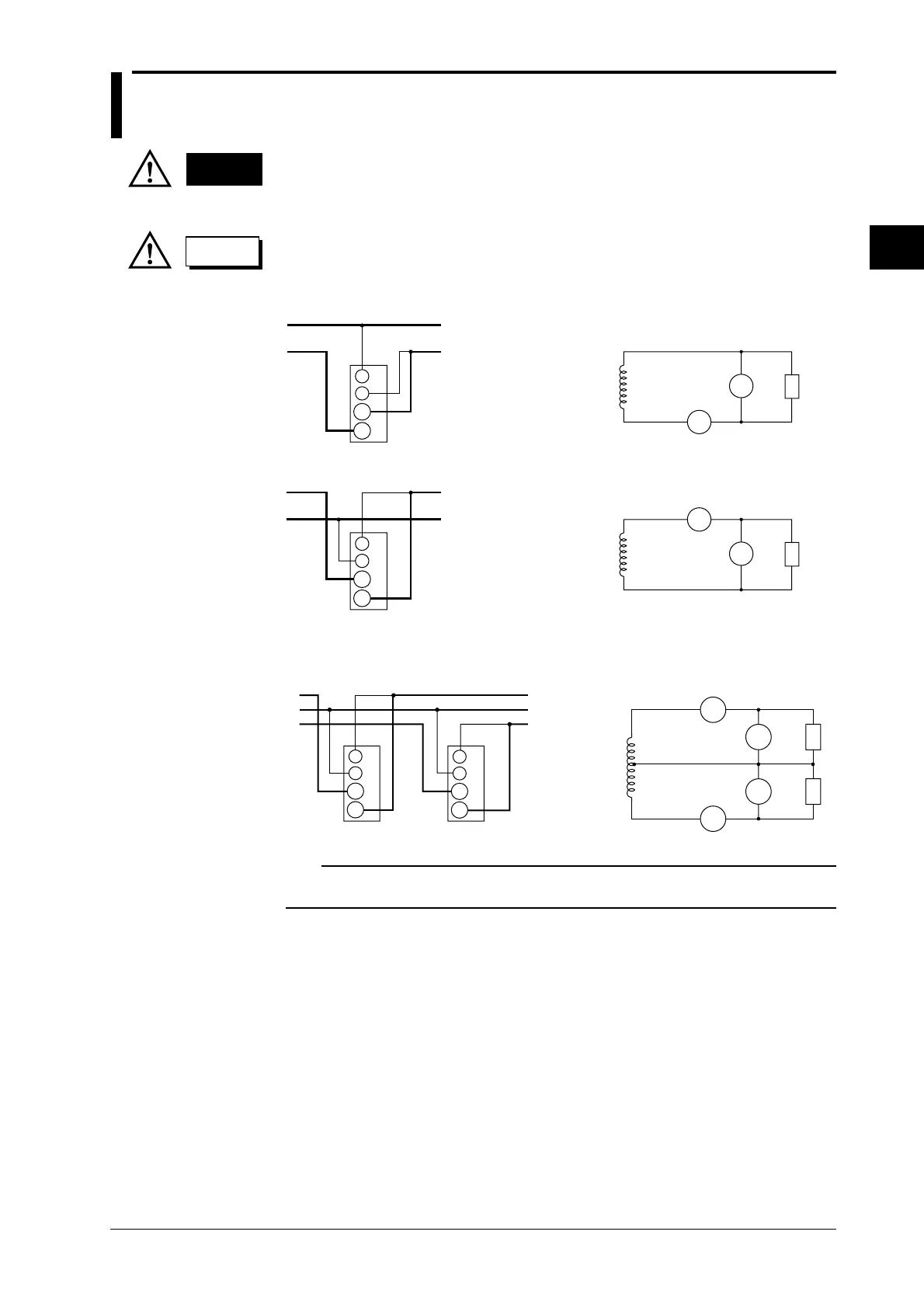
3.4 Wiring the Measurement Circuit
WARNING
• When applying a current to be measured directly to the input terminals of
the instrument, disconnect the input cable of the external sensor. A voltage
might be generated by the external sensor input terminal when connected.
CAUTION
• A load current flows in the thick lines show in the diagrams; therefore, a
wire with sufficient current capacity must be used for these lines.
Wiring diagram for single-phase, two-wire system (253401, 253502, 253503)
SOURCE
LOAD
A
V
±
±
Input terminal
(ELEMENT)
SOURCE
LOAD
SOURCE
LOADV
A
±
± A
V
LOADV
±
V
A
±
A
SOURCE
A
V
±
±
Input terminal
(ELEMENT)
Wiring diagram for single-phase, three-wire system (253502, 253503)
SOURCE
LOAD
SOURCE
LOAD
V
A
±
±
A
V
V
±
V
A
±
A
N
1
3
1
3
N
A
V
±
±
Input terminal
(ELEMENT1)
A
V
±
±
Input terminal
(ELEMENT3)
Note
The wire connected from the source the ± current terminal must be routed as close as possible to the
ground potential in order to minimize measurement error.
 Loading...


