IM 253401-01E
3-6
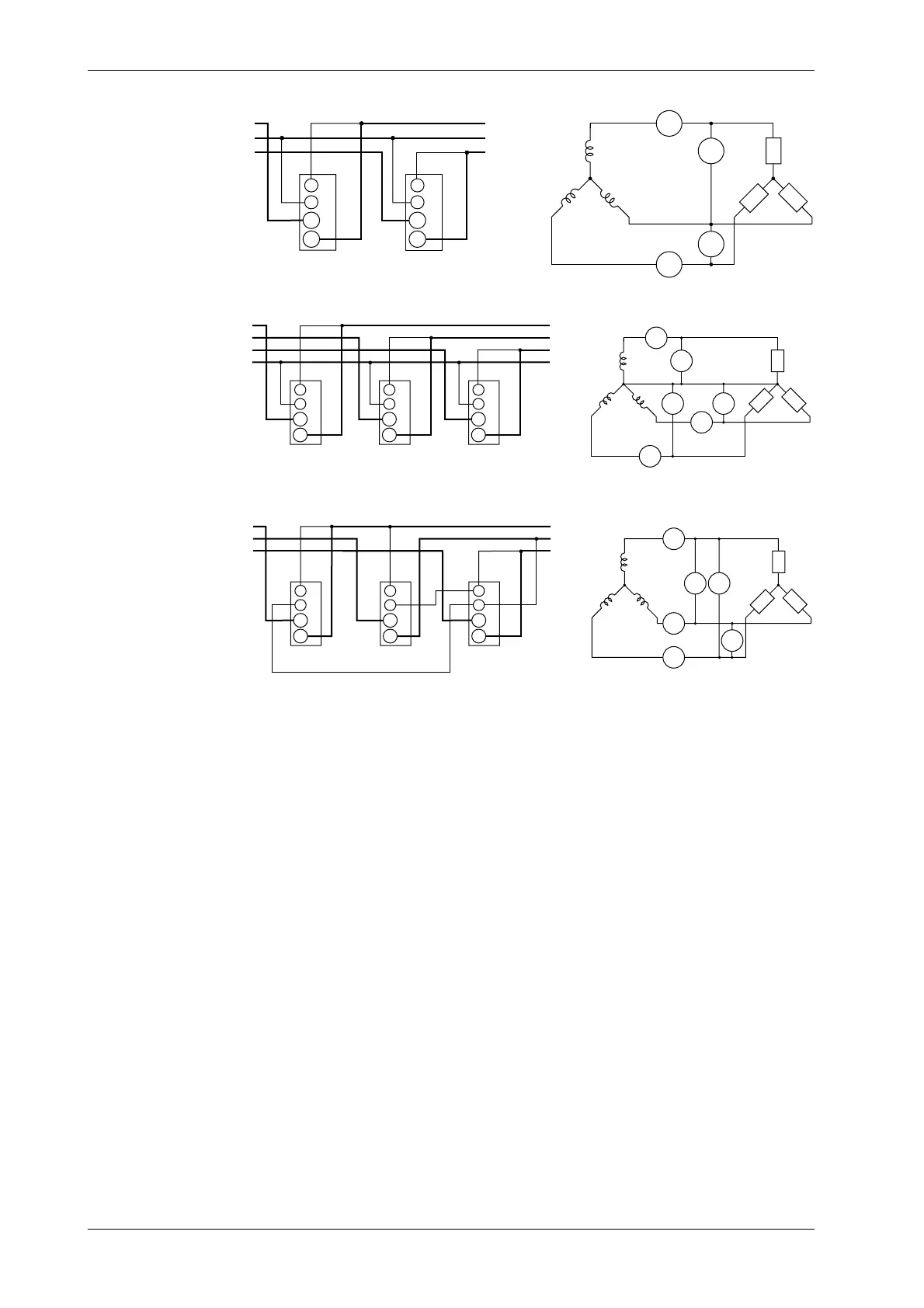
Wiring diagram for three-phase, three-wire system (253502, 253503)
SOURCE
LOAD
SOURCE
LOAD
A
±
A
±
A
±
A
S
1
3
R
T
V
±
V
V
V
3
1
R
ST
A
V
±
±
Input terminal
(ELEMENT3)
A
V
±
±
Input terminal
(ELEMENT1)
Wiring diagram for three-phase, four-wire system (253503)
A
V
±
±
Input terminal
(ELEMENT3)
LOAD
SOURCE
LOAD
A
±
A
A
±
A
1
3
R
ST
SOURCE
S
R
T
N
V
±
V
1
±
V
V
3
±
V
V
2
A
±
A
2
N
A
V
±
±
Input terminal
(ELEMENT1)
A
V
±
±
Input terminal
(ELEMENT2)
Wiring diagram for three-voltage, three-current system (253503)
LOAD
SOURCE
LOAD
A
±
A
A
±
A
1
3
R
ST
SOURCE
S
R
T
V
±
V
1
±
V
V
3
±
V
V
2
A
±
A
2
A
V
±
±
Input terminal
(ELEMENT3)
A
V
±
±
Input terminal
(ELEMENT1)
A
V
±
±
Input terminal
(ELEMENT2)
3.4 Wiring the Measurement Circuit

 Loading...


