IM 253401-01E
11-10
11.6 Setting the Output Items
Relevant Keys
SCALING
AVG FILTER
STORE
RECALL
HARMONICS
SAMPLE
V OVER
A OVER
MODE
RMS
V MEAN
DC
A
B
C
hour
hour
min
min sec
VVA
m
Ak
var
MW
TIME
VPF
m
Ak
deg
MW
%
FUNCTION
AUTO AUTO
MODE
1Φ3W
VHz
m
Ak
h
MW
TRIG
V RANGE A RANGE HOLD
ENTER
INTEGRATOR
START
HARMONICS MEMORY INTEG SET
STOP RESET
REMOTE
INTERFACE OUTPUT
LOCAL
SETUP
h
SHIFT
WIRING
3Φ4W
3Φ3W
3V3A
ELEMENT
123
FUNCTION ELEMENT
123
FUNCTION ELEMENT
123
* Shows the operation panel of the WT130. For the differences
between WT110 and WT130, refer to section 2.2, page 2-2, 2-3
Displays
relevant
keys and
indicators
Operating Procedure
SHIFT
SETUP
OUTPUT
ENTER
3.
Selecting communication
(Display C)
Selecting normal
(Display C)
2.
ENTER
5.
4.
Selecting output format
(Display C)
ENTER
7.
End
6.
Setting output channel
(Display C)
8.,14.
ENTER
9.
Setting output item
(Display C)
10.
ENTER
ENTER
15.
End
13.
*1
ENTER
10. Sets the A column
11. Moves to the B column
12. Select from 1 to 4
SHIFT
(Selecting desired item)
(Selecting
default
setting)
*1 When you press the key at step 13, the output
channel displayed at display B will change to the next
channel, i.e. from ch1 to ch2 and so forth.
*2 Displayed on WT110/WT130 with ROM version 2.01 or
later.
1.
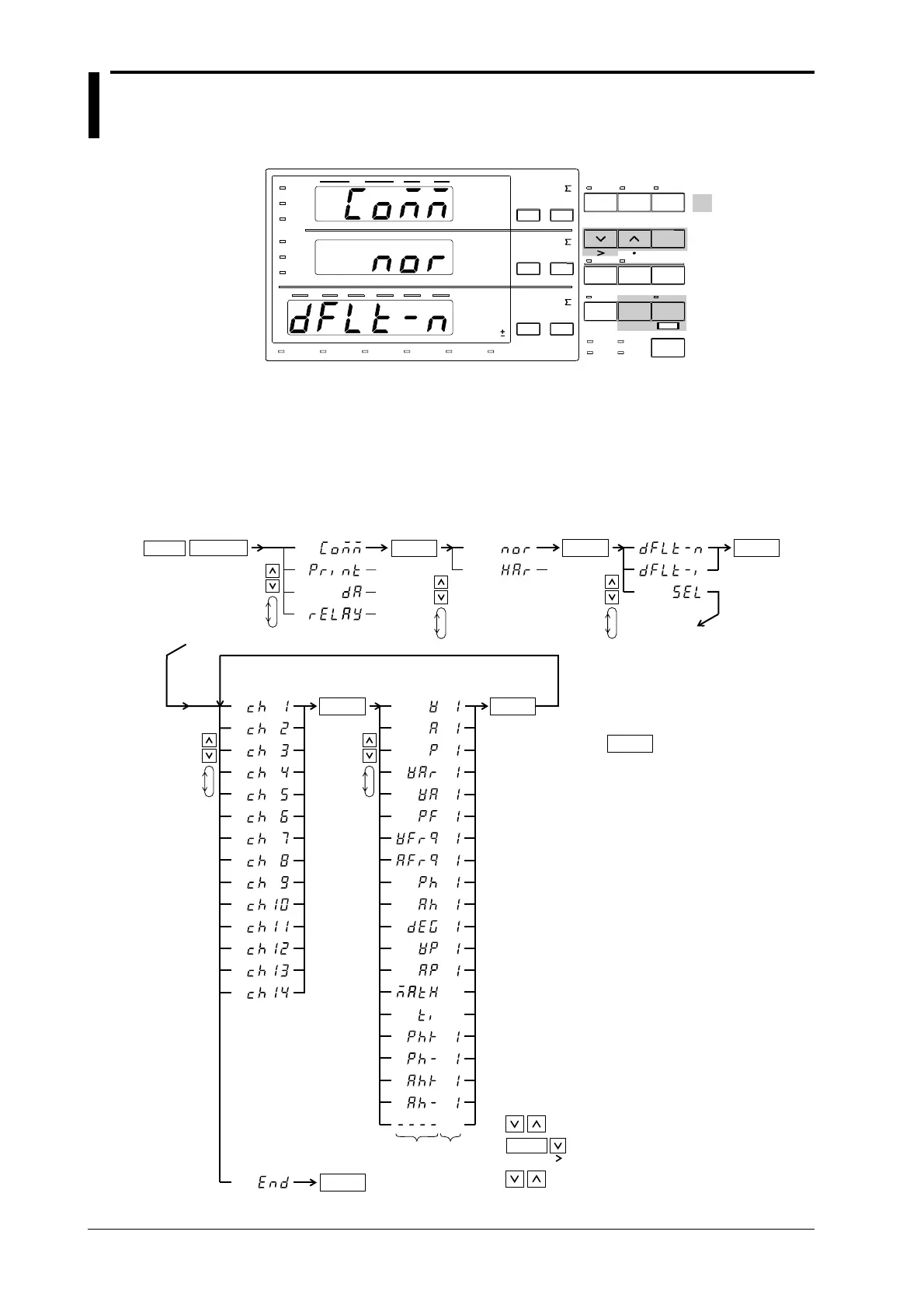
• Setting the Output Item in case of Normal Measurement
• Perform operations following the thick line in the below menu.
• Press the ENTER key to confirm the selection or setting.
• When you want to leave the current menu during operation, press the key described
under step 1. The confirmed settings made until that point will be kept.
A
B
*2
*2
*2

 Loading...


