IM 253401-01E
4-1
4
Setting Measurement Conditions
4.1 Selecting the Measurement Mode
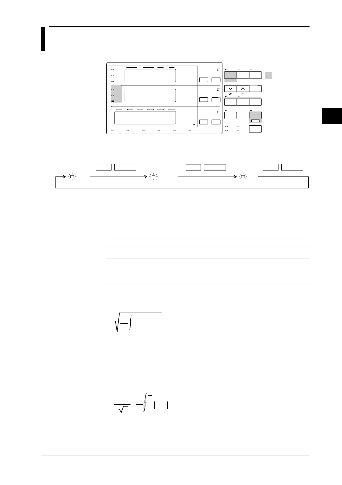
Relevant Keys
SCALING
AVG FILTER
STORE
RECALL
HARMONICS
SAMPLE
V OVER
A OVER
MODE
RMS
V MEAN
DC
A
B
C
hour
hour
min
min sec
VVA
m
Ak
var
MW
TIME
VPF
m
Ak
deg
MW
%
FUNCTION
AUTO AUTO
MODE
1Φ3W
VHz
m
Ak
h
MW
TRIG
V RANGE A RANGE HOLD
ENTER
INTEGRATOR
START
HARMONICS MEMORY INTEG SET
STOP RESET
REMOTE
INTERFACE OUTPUT
LOCAL
SETUP
h
SHIFT
WIRING
3Φ4W
3Φ3W
3V3A
ELEMENT
123
FUNCTION ELEMENT
123
FUNCTION ELEMENT
123
*Shows the operation panel of the WT130. For the differences
between WT110 and WT130, refer to section 2.2, page 2-2, 2-3
Displays
relevant
keys and
indicator
Operating Procedure
RMS V MEAN DC
MODE
V RANGE
SHIFT
MODE
V RANGE
SHIFT
MODE
V RANGE
SHIFT
Explanation
Measurement Mode
One of the following measurement modes can be selected for measurement of voltage and
current. The initial value is “RMS”.
Indicator Voltage Current
RMS Measures and displays true Measures and displays true RMS
RMS value value
V MEAN Displays rectified mean value Measures and displays
calibrated to the RMS value true RMS value
DC Displays DC value obtained by Displays DC value obtained by averaging the input
averaging the input signal signal
Theoretical Equations
• RMS
This mode is selected to display input voltage or current as a true RMS value.
1
T
0
T
f(t)
2
dt
f (t) : input signal
T:one period of the input signal
•V MEAN
This mode is selected to display input voltage or current as a rectified mean value calibrated
to the RMS value. Since a sine wave is used for calibration, the value displayed will be the
same as that obtained in RMS mode if a sine wave is measured. The value displayed will be
different from that obtained in RMS mode if a distorted or DC waveform is measured.
π
2
2
•
2
T
0
T
2
f
(t)
dt
f (t) : input signal
T:one period of the input signal
•DC
This mode is selected when the input voltage or current is DC. The input signal is averaged
and the result is displayed.

 Loading...


