IM 253401-01E
App2-2
Appendix 2.2 Program Format
Appendix 2.2 Program Format
2.2.2 Messages
Blocks of message data are transferred between the controller
and this instrument during communications. Messages sent
from the controller to this instrument are called program
messages, and messages sent back from this instrument to the
controller are called response messages.
If a program message contains a query command, i.e. a
command which requests a response, this instrument returns a
response message. A single response message is always
returned in reply to a program message.
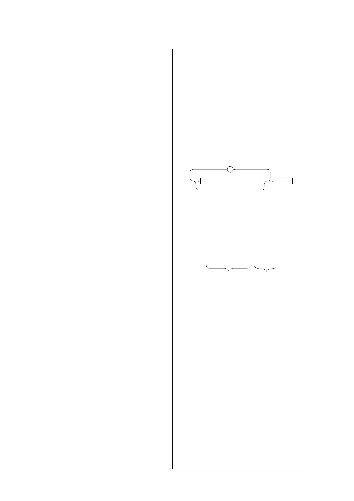
Program Messages
As explained above, the data (message) sent from the
controller to this instrument is called a program message. The
format of a program message is shown below.
<PMT>
;
Program message unit
<Program message unit>
A program message consists of zero or more program message
units; each unit corresponds to one command. This instrument
executes commands one by one according to the order in
which they are received.
Program message units are delimited by a “
;
”.
For a description of the format of the program message unit,
refer to the explanation given further below.
Example :
CONFIGURE:MODE RMS;FILTER ON<PMT>
<PMT>
PMT is a terminator used to terminate each program message.
The following three types of terminator are available.
NL
(New Line) : Same as LF (Line Feed). ASCII code
“
0AH
” is used.
^END
: END message defined in IEEE488.1. (EOI
signal)
(The data byte sent with an END message
will be the final item of the program
message unit.)
NL^END
: NL with an END message attached
(NL is not included in the program
message unit.)
2.2.1 Symbols Used in Syntax
Descriptions
Symbols which are used in the syntax descriptions in
Appendix 2.3 are shown below. These symbols are referred to
as BNF notation (Backus-Naur Form). For detailed
information, refer to pages App2-6 to App2-7.
Symbol Description Example Example
< > Defined value CHANnel<x> <x>=1, 2 CHANNEL2
{} One of the options in MODE {AND|OR} MODE AND
{} is selected.
| Exclusive OR MODE {AND|OR} MODE AND
[ ] Abbreviated :MEASure[:MODE] {<NRf>}
... may be repeated
 Loading...


